Toyota RAV4 (XA40) 2013-2018 Service Manual: Diagnosis system
- Bus check
- Select "bus check" from the "obd / mobd menu" screen.
Hint:
The ecus and sensors that are properly connected to the can communication system can be displayed using the intelligent tester via can vim.
- Press "enter" on the intelligent tester via can vim.
- The screen displayed the ecus and sensors that are properly connected to the can communication system.
Hint:
There is a communication stop in the system of any properly connected ecus or sensors that are not displayed (see page ca-10).
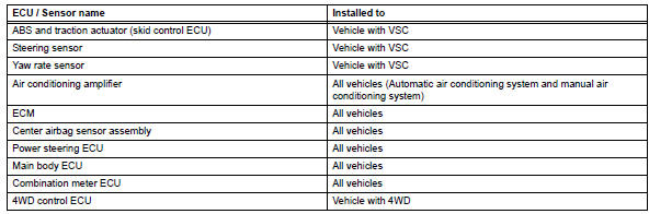
- Check installed systems (ecus and sensors) that use can communication
- System (ecus and sensors) that use can communication vary depending on the vehicle's optional settings. Check which systems (ecus and sensors) are installed on the vehicle.
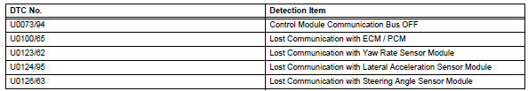
- Dtc table by ecu
Hint:
- In the can communication system, can communication system dtcs output by the ecu can be displayed by using the intelligent tester.
- If can communication system dtcs are output, the
trouble cannot be determined solely from the dtcs.
Perform troubleshooting according to "how to proceed with troubleshooting" (see page ca-8).
- Abs and traction actuator (skid control ecu)
Hint:
Dtc communication uses the can communication system.
- Power steering ecu
Hint:
Dtc communication uses the can communication
system.
- Ecm
Hint:
Dtc communication uses the can communication
system.
- Air conditioning amplifier for vehicle with air conditioning (automatic air conditioning system and manual air conditioning system).
Hint:
Dtc communication uses the can communication
system.![]()
- Combination meter ecu
Hint:
Dtc communication uses the can communication
system.
- 4Wd control ecu
For vehicle with 4wd only.
Hint:
Dtc communication uses the can communication
system.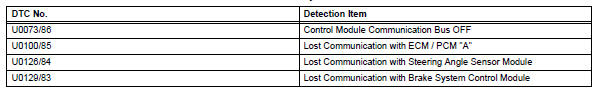
- Main body ecu
Hint:
The center airbag sensor is connected to the can communication system but can communication dtcs are not output.
- Center airbag sensor
Hint:
The center airbag sensor is connected to the can communication system but can communication dtcs are not output.
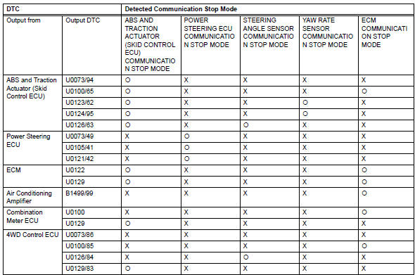
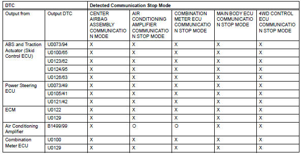
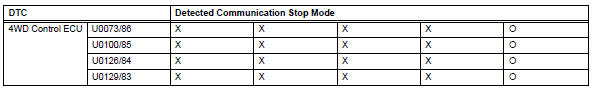
- Dtc combination table
Hint:
- O: Outputs under condition shown in table above
- X: not output
Hint:
- O: Outputs under condition shown in table above
- X: not output
- Check the stop mode by using the results of the bus check for the center airbag sensor (see page ca- 69) and main body ecu (see page ca-64).
- Perform troubleshooting according to the combination of dtcs output.
- Abs and traction actuator (skid control ecu) communication stop mode: (see page ca-42)
- Power steering ecu communication stop mode: (see page ca-49)
- Steering angle sensor communication stop mode: (see page ca-52)
- Yaw rate sensor communication stop mode: (see page ca-55)
- Ecm communication stop mode: (see page ca-58)
- Air conditioning amplifier communication stop mode: (see page ca-45)
- Combination meter ecu communication system: (see page ca-67)
- 4Wd control ecu communication stop mode: (see page ca-72)
 Check 4wd control ecu (for 4wd)
Notice:
Turn the ignition switch off before measuring the
resistances of the main wire and branch wire.
After the ignition switch is turned off, check that the
key reminder warning system an ...
 Fail-safe chart
Fail-safe function
When communication fails in any of the main wires
(communication lines) due to a short circuit or other
causes, the fail-safe function, which is specified for
each sy ...
Other materials:
Making a call
Once a bluetooth® phone is registered, you can make a call
using the following procedure:
Dialing
Display the phone screen.
Select the “dial pad” tab and enter a phone number.
To delete the input phone number, select
.
For the first digit, you can enter
by selecting &nb ...
Stuck in deceleration sensor
Description
The skid control ecu receives signals from the yaw rate and deceleration
sensor via the can
communication system.
The yaw rate sensor has a built-in deceleration sensor and detects the vehicle's
condition using 2 circuits
(gl1: g sensor 1, gl2: g sensor 2).
If there is t ...
Blower unit
Components
Removal
Disconnect cable from negative battery
terminal
Caution:
Wait at least 90 seconds after disconnecting the
cable from the negative (-) battery terminal to
prevent airbag and seat belt pretensioner activation.
Remove upper instrument panel
Remove the upper ...
