Toyota RAV4 (XA40) 2013-2018 Service Manual: Diagnosis system
- Check dlc3
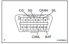
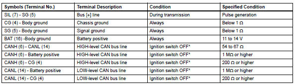
- Check the dlc3: the power steering ecu uses can (iso11898-1) and iso9141-2 for communication protocol. The terminal arrangement of the dlc3 complies with sae j1962 and matches the iso9141-2 format.
Notice:
*: Before measuring the resistance, leave the vehicle as is for at least 1 minute and do not operate the ignition switch, other switches or the doors.
If the result is not as specified, the dlc3 may have a malfunction. Repair or replace the harness and connector.
Hint:
Connect the cable of the intelligent tester to the dlc3, turn the ignition switch on and attempt to use the tester. If the display indicates that a communication error has occurred, there is a problem either with the vehicle or with the tester.
- If communication is normal when the tester is connected to another vehicle, inspect the dlc3 of the original vehicle.
- If communication is still not possible when the tester is connected to another vehicle, the problem may be in the tester itself. Consult the service department listed in the tester's instruction manual.
- Warning light
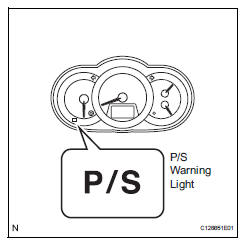
- When a problem occurs in the electronic power steering system, the p/s warning light on the combination meter comes on to inform the driver of the problem.
 Terminals of ecu
Check power steering ecu
Hint:
Measurements cannot be performed on the c connector
side of the power steering ecu.
Measure the voltage and resistance of the
connectors.
...
 Dtc check / clear
Check dtc
When using intelligent tester:
Connect the intelligent tester (with can vim) to
the dlc3.
Turn the ignition switch on and press the
intelligent tester main switch on ...
Other materials:
Abnormal temperature inside
Description
The tire pressure warning valve and transmitter measures tire internal
temperature as well as tire
pressure, and transmits the information to the tire pressure monitor receiver
along with the transmitter id.
If the measured temperature is out of the specified range, the tire ...
Rear occupant classification sensor rh collision detection
Description
Dtc b1788 is output when the occupant classification ecu receives a collision
detection signal sent by
the rear occupant classification sensor rh when an accident occurs.
Dtc b1788 is also output when the front seat rh is subjected to a strong impact,
even if an actual
acci ...
Disassembly
Hint:
Use the same procedures for the rh side and lh side.
The procedures listed below are for the lh side.
Remove no. 1 Rear seat reclining cover lh
Remove the 2 screws.
Using a screwdriver, detach the 5 claws and remove
the cover.
Hint:
Tape the screwdriver tip before ...
