Toyota RAV4 (XA40) 2013-2018 Service Manual: Dtc check / clear
- Check dtc
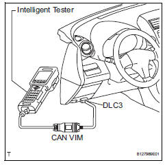
- When using intelligent tester:
- Connect the intelligent tester (with can vim) to the dlc3.
- Turn the ignition switch on and press the intelligent tester main switch on.
- Read the dtcs by following the prompts on the intelligent tester.
Hint:
Refer to the intelligent tester operator's manual for further details.
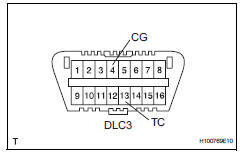
- When not using intelligent tester:
- Using sst, connect terminals 13 (tc) and 4
(cg) of the dlc3.
Sst 09843-18040
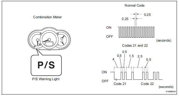
- Turn the ignition switch on.
- Read and write down any dtcs indicated by the
p/s warning light on the combination meter.
Refer to the chart below for examples of a normal code and dtcs 21 and 22.
Hint:
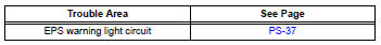
- If the p/s warning light does not blink to
display any dtcs set or the normal code,
inspect the circuit shown in the table below.
- If two or more malfunctions are detected simultaneously, dtcs will be displayed in ascending numerical order.
- Refer to the diagnostic trouble code chart (see page ps-16) for dtc information.
- Clear dtc
- When using intelligent tester:
- Connect the intelligent tester (with can vim) to the dlc3.
- Turn the ignition switch on and press the intelligent tester main switch on.
- Clear the dtcs by following the prompts on the intelligent tester.
- Turn the ignition switch off.
- Disconnect the intelligent tester from the dlc3.
- When not using intelligent tester:
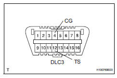
- Using sst, connect terminals 12 (ts) and 4
(cg) of the dlc3.
Sst 09843-18040
- Turn the ignition switch on.
- Disconnect the sst check wire from terminal 4 (cg) and reconnect it, and repeat this procedure 4 times or more within 8 seconds.
- Check that the p/s warning light blinking pattern is the normal code.
- Turn the ignition switch off.
- Remove sst from the dlc3.
 Diagnosis system
Check dlc3
Check the dlc3:
the power steering ecu uses can (iso11898-1)
and iso9141-2 for communication protocol. The
terminal arrangement of the dlc3 complies with
sae j1962 and ...
 Freeze frame data
Freeze frame data
Notice:
It is difficult to show the specified values
(judgment values) clearly because freeze frame
data values change significantly due to
differences in measurement ...
Other materials:
Brk relay
On-vehicle inspection
Inspect brk relay
Remove the brk relay from the engine room no. 1
Relay block.
Measure the resistance of the relay.
Standard resistance
If the result is not as specified, replace the relay. ...
Exterior
The shape of the headlights may differ depending on the grade, etc.
Side doors
Locking/unlocking
Opening/closing the side windows
Locking/unlocking by using the key
Warning messages
Back door
Locking/unlocking
Opening from inside the cabin*
Opening from outside
Warning messages
Outs ...
Luggage compartment features
Cargo hooks
Raise the hook to use.
The cargo hooks are provided for
securing loose items.
WARNING
â– When cargo hooks are not in
use
To avoid injury, always return the
hooks to their stowed positions
when not in use.
Deck board
â– Flipping the deck board
upside down
The deck board can be flipped
...
