
Toyota RAV4 (XA40) 2013-2018 Service Manual: Diagnosis system
- Description
The ecm controls the function of cruise control on this vehicle. Data of the cruise control or dtc can be read from the dlc3 of the vehicle. When trouble occurs with cruise control, check that the cruise main indicator does not come on but dtc inspection is performed.
Therefore, when there seems to be a problem with the cruise control, use the intelligent tester (with can vim) or sst to check and troubleshoot it.
- Check dlc3
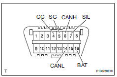
- The ecm uses iso 15765-4 for communication.
The terminal arrangement of the dlc3 complies with sae j1962 and matches the iso 15765-4 format.
Notice:
*: Before measuring the resistance, leave the vehicle as is for at least 1 minute and do not operate the ignition switch, other switches or doors.
If the result is not as specified, the dlc3 may have a malfunction. Repair or replace the harness and connector.
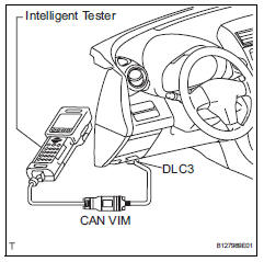
Hint:
Connect the cable of the intelligent tester (with can vim) to the dlc3, turn the ignition switch on and attempt to use the tester. If the display indicates that a communication error has occurred, there is a problem either with the vehicle or with the tester.
- If communication is normal when the tester is connected to another vehicle, inspect the dlc3 of the original vehicle.
- If communication is still not possible when the tester is connected to another vehicle, the problem may be in the tester itself. Consult the service department listed in the tester's instruction manual.
- Check indicator
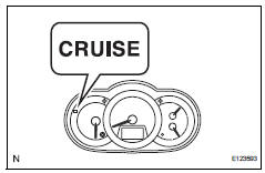
- Turn the ignition switch on.
- Check that the cruise main indicator light illuminates when the cruise control main switch is turned on, and that the indicator light goes off when the main switch is turned off.
Hint:
- If the indicator check result is not normal, proceed to troubleshooting for the combination meter section (see page me-15).
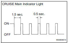
- If a malfunction occurs in the speed sensor or
stop light switch, etc. During cruise control
driving, the ecm activates the auto cancel of
the cruise control and the cruise main indicator
light blinks to inform the driver of a malfunction.
At the same time, the malfunction is stored in memory as a diagnostic trouble code.
 Terminals of ecm
Check ecm
Disconnect the a9 and b30 connectors.
Measure the voltage and resistance of the wire
harness side connectors.
If the result is not as specified, there may be a
malfu ...
 Dtc check / clear
Check dtc (using intelligent tester)
Connect the intelligent tester (with can vim) to the
dlc3.
Turn the ignition switch on.
Read the dtcs by following the directions on the
teste ...
Other materials:
Using the aux port
To use the aux port, connect a portable player, press the
“audio� button, then select “aux� to display the audio control
screen.
Connecting a portable audio player
Operating portable audio players connected to the audio system
The volume can be adjusted using the vehicle’s audio contr ...
Tire and wheel system
Inspection
Inspect tire
Check the tires for wear and proper inflation
pressure.
Standard cold tire inflation pressure:
220 kpa (2.2 Kgf/cm2, 32 psi)
Using a dial indicator, check the runout of the tires.
Standard tire runout:
1.0 Mm (0.039 In.) Or less
Rotate tire
...
Ecm communication stop mode (2006/01- )
Description
Wiring diagram
Inspection procedure
Notice:
Turn the ignition switch off before measuring the resistances of the
main wire and branch
wire.
After the ignition switch is turned off, check that the key reminder
warning system and light
reminder warning system ...
