Toyota RAV4 (XA40) 2013-2018 Service Manual: Diagnosis system
- Description
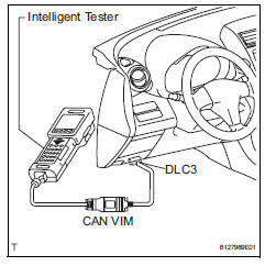
- Key reminder warning system data can be read through the data link connector 3 (dlc3) of the vehicle. When the system seems to be malfunctioning, use the intelligent tester (with can vim) to check for malfunctions and perform repairs.
- Check dlc3
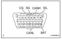
The vehicle's ecm uses iso 15765-4 communication protocol. The terminal arrangement of the dlc3 complies with iso 15031-03 and matches the iso 15765-4 format.
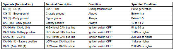
Notice:
*: Before measuring the resistance, leave the vehicle as is for at least 1 minute and do not operate the ignition switch, other switches or doors.
If the result is not as specified, the dlc3 may have a malfunction. Repair or replace the harness and connector.
Hint:
Connect the cable of the intelligent tester (with can vim) to the dcl3, turn the ignition switch on and attempt to use the tester. If the display indicates that a communication error has occurred, there is a problem either with the vehicle or with the tester.
- If communication is normal when the tester is connected to another vehicle, inspect the dlc3 on the original vehicle.
- If communication is still not possible when the tester is connected to another vehicle, the problem may be in the tester itself. Consult the service department listed in the tester's instruction manual.
 Terminals of ecu
Check combination meter assembly
Measure the voltage and resistance of the
connector.
Check instrument panel junction block (main body ecu)
Measure the voltage and r ...
 Data list / active test
Read data list
Hint:
Using the intelligent tester's data list allows switch,
actuator and other item values to be read without
removing any parts. Reading the data list early in
troubleshoot ...
Other materials:
Open in stop light switch circuit
Description
The skid control ecu detects the brake operating conditions through a signal
transmitted by the stop light
switch. The skid control ecu incorporates an open circuit detection circuit.
This dtc is set under either of
the following conditions:
An open is detected in the stop lig ...
Power seat switch
Inspection
Inspect front power seat switch
Measure the resistance between the terminals when
each switch is operated.
Standard resistance
Slide switch
Front vertical switch
Lifter switch
Reclining switch
If the result is not as specified, replace the switch. ...
Seat belts
Make sure that all occupants
are wearing their seat
belts before driving the
vehicle.
WARNING
Observe the following precautions
to reduce the risk of injury in the
event of sudden braking, sudden
swerving or an accident.
Failure to do so may cause death
or serious injury.
â– Wearing a seat belt
E ...
