Toyota RAV4 (XA40) 2013-2018 Service Manual: Disassembly
- Remove radio setting condenser

- Remove the bolt and condenser.
- Remove oil pressure switch
- Using a 24 mm deep socket wrench, remove the sensor.
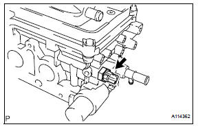
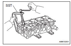
- Remove engine coolant temperature sensor
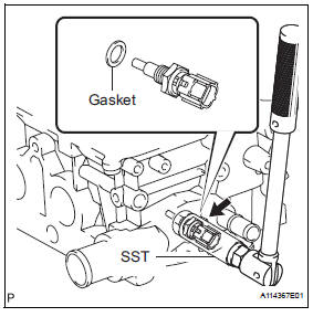
- Using sst, remove the sensor and gasket.
Sst 09817-33190
- Remove camshaft position sensor
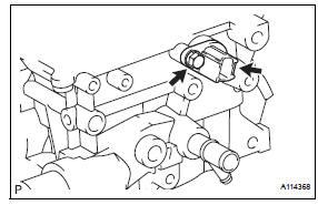
- remove the bolt and sensor.
- Remove no. 2 Camshaft bearing
- Remove the no. 2 Camshaft bearing.
- Remove no. 1 Camshaft bearing
- Remove the no. 1 Camshaft bearing.
- Remove valve lifter
Hint:
Arrange the valve lifters in the correct order.
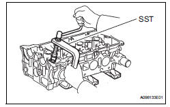
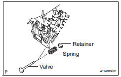
- Remove intake valve
- Place the cylinder head on wooden blocks.
- Using sst, compress the spring, then remove the 2 retainer locks.
Sst 09202-70020 (09202-00010)
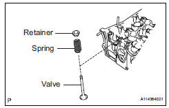
- Remove the retainer, spring and valve from the cylinder head.
Hint:
Arrange the removed parts in the correct order.
- Remove exhaust valve
- Place the cylinder head on wooden blocks.
- Using sst, compress the spring, then remove the 2 retainer locks.
Sst 09202-70020 (09202-00010)
- Remove valve spring seat
- Using compressed air and a magnetic finger, remove the spring seat by blowing air.
Hint:
Arrange the valves, valve springs, spring seats and spring retainers in the correct order.
- Remove valve stem oil seal
- Using needle-nose pliers, remove the 16 oil seals.
 Removal
Discharge fuel system pressure (see page
fu-9)
Disconnect cable from negative battery
terminal
Caution:
Wait at least 90 seconds after disconnecting the
cable from the negative (-) batte ...
 Inspection
Inspect cylinder head for warpage
Using a precision straightedge and feeler gauge,
measure the warpage of the contact surfaces of the
cylinder block and manifolds.
Maximum warpage: ...
Other materials:
Precaution
Inspection procedure for vehicle involved
in accident
Perform the zero point calibration and sensitivity
check if any of the following conditions apply.
The occupant classification ecu is replaced.
Accessories (seat cover etc.) Are installed.
The front passenger seat is remove ...
Mil circuit
Description
The mil (malfunction indicator lamp) is used to indicate vehicle malfunction
detections by the ecm.
When the ignition switch is turned on, power is supplied to the mil circuit, and
the ecm provides the
circuit ground which illuminates the mil.
The mil operation can be checked ...
Other interior features
Sun visors
To set the visor in the forward
position, flip it down.
To set the visor in the side
position, flip down, unhook,
and swing it to the side.
To use the side extender (if
equipped), place the visor in
the side position, then slide it
backward.
Vanity mirrors
Slide the cover to o ...
