Toyota RAV4 (XA40) 2013-2018 Service Manual: Disassembly (2006/01- )
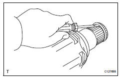
- Remove front axle inboard joint boot no. 2 Clamp
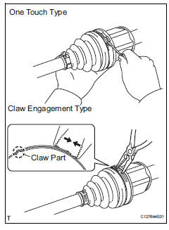
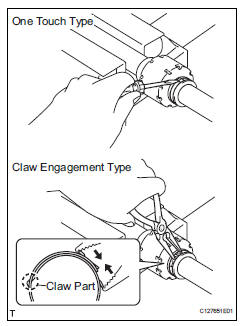
- One touch type: using a screwdriver, remove the inboard joint boot clamp, as shown in the illustration.
- Claw engagement type: using needle-nose pliers, remove the inboard joint boot clamp, as shown in the illustration.
- Remove front axle inboard joint boot clamp
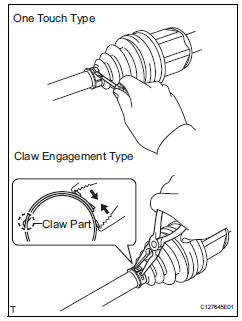
- One touch type: using a screwdriver, remove the inboard joint boot clamp, as shown in the illustration.
- Claw engagement type: using needle-nose pliers, remove the inboard joint boot clamp, as shown in the illustration.
- Remove front axle inboard joint boot
- Remove the boot from the inboard joint.
- Remove front drive inboard joint assembly lh
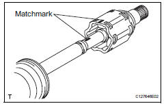
- Remove any old grease from the inboard joint.
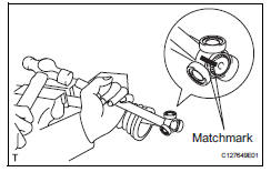
- Put matchmarks on the inboard joint and outboard joint shaft.
Notice:
Do not punch the marks.
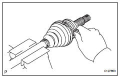
- Remove the inboard joint from the outboard joint shaft.
- Using a snap ring expander, remove the shaft snap ring.
- Put matchmarks on the outboard joint shaft and tripod joint.
Notice:
Do not punch the marks.
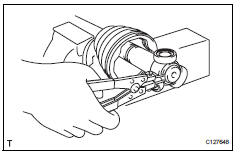
- Using a brass bar and hammer, tap out the tripod joint from the outboard joint shaft.
Notice:
Do not tap the rollers.
- Remove the inboard joint boot.
- Remove front drive inboard joint assembly rh
Hint:
Use the same procedures described for the lh side.
- Remove front drive shaft damper clamp lh
- One touch type: using a screwdriver, remove the drive shaft damper clamp, as shown in the illustration.
- Claw engagement type: using needle-nose pliers, remove the drive shaft damper clamp, as shown in the illustration.
- Remove front drive shaft damper lh
- Remove the front drive shaft damper from the outboard joint shaft.
- Remove front axle outboard joint boot no. 2 Clamp
- Using a screwdriver, remove the outboard joint boot clamp, as shown in the illustration.
- Remove front axle outboard joint boot clamp
- Using a screwdriver, remove the outboard joint boot clamp, as shown in the illustration.
- Remove front axle outboard joint boot
- Remove the outboard joint boot from the outboard joint shaft.
- Remove any old grease from the outboard joint.
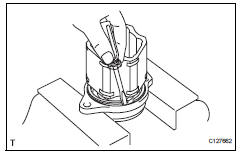
- Remove front drive shaft hole snap ring lh
- Using a screwdriver, remove the hole snap ring.
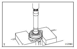
- Remove front drive shaft dust cover lh
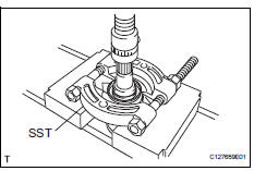
- Using sst and a press, press out the shaft dust cover.
Sst 09950-00020
Notice:
Be careful not to drop the inboard joint.
- Remove front drive shaft dust cover rh
Hint:
Use the same procedures described for the lh side.
- Remove drive shaft bearing case (for rh)
- Using a screwdriver, remove the bearing case snap ring.
- Using a press, press out the drive shaft bearing case.
Hint:
Be careful not to drop the inboard joint.
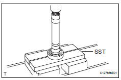
- Remove front drive shaft dust cover (for rh)
- Using sst and a press, press out the drive shaft dust cover.
Sst 09950-00020
Notice:
Be careful not to drop the inboard joint.
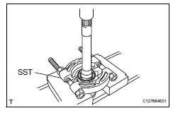
- Remove front drive shaft bearing
- Using a snap ring expander, remove the snap ring.
- Using sst and a press, press out the drive shaft bearing.
Sst 09527-10011
- Remove the bearing case snap ring.
 Disassembly (2005/11-2006/01)
Remove front axle inboard joint boot no. 2 Clamp lh
One touch type:
Using a screwdriver, remove the inboard joint
boot clamp, as shown in the illustration.
Claw engagement t ...
 Reassembly (2005/11-2006/01)
Install drive shaft bearing case subassembly
Using sst and a press, press in the drive shaft
bearing case to the inboard joint rh.
Sst 09527-10011, 09710-04081
Notice:
The bearing ...
Other materials:
Inside rear view mirror
The rear view mirror's position
can be adjusted to
enable sufficient confirmation
of the rear view.
Adjusting the height of
rear view mirror
The height of the rear view mirror
can be adjusted to suit your
driving posture.
Adjust the height of the rear
view mirror by moving it up and
down.
WARNING
...
Before driving
Floor mat
Use only floor mats designed specifically for vehicles of the same
model and model year as your vehicle. Fix them securely in place
onto the carpet.
Insert the retaining hooks (clips)
into the floor mat eyelets.
Turn the upper knob of each
retaining hook (clip) to secure
t ...
Installation
Install knock sensor
Install the sensor with the nut.
Torque: 20 n*m (205 kgf*cm, 15 ft.*Lbf)
Notice:
Make sure that the knock sensor is in the
correct position.
Connect the sensor connector.
Install intake manifold insulator
install the intake manifold insulat ...
