Toyota RAV4 (XA40) 2013-2018 Service Manual: Disassembly (2005/11-2006/01)
- Remove front axle inboard joint boot no. 2 Clamp lh
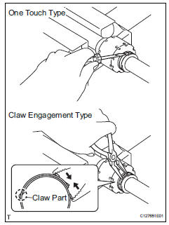
- One touch type:
- Using a screwdriver, remove the inboard joint boot clamp, as shown in the illustration.
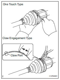
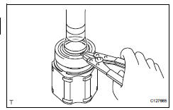
- Claw engagement type:
- Using needle-nose pliers, remove the inboard joint boot clamp, as shown in the illustration.
- Remove front axle inboard joint boot no. 2 Clamp rh
Hint:
Use the same procedures described for the lh side.
- Remove front axle inboard joint boot clamp lh
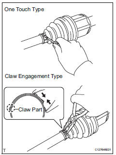
- One touch type:
- Using a screwdriver, remove the inboard joint boot clamp, as shown in the illustration.
- Claw engagement type:
Using needle-nose pliers, remove the inboard joint boot clamp, as shown in the illustration.
- Remove front axle inboard joint boot clamp rh
Hint:
Use the same procedures described for the lh side.
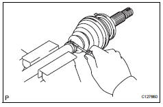
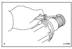
- Remove front axle inboard joint boot
- Remove the boot from the inboard joint.
- Remove front drive inboard joint assembly lh
- Remove any old grease from the inboard joint.
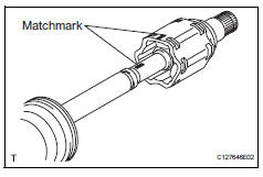
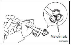
- Put matchmarks on the inboard joint and outboard joint shaft.
Notice:
Do not punch the marks.
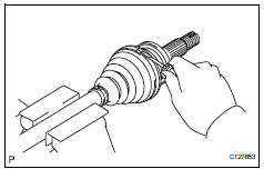
- Remove the inboard joint from the outboard joint shaft.
- Using a snap ring expander, remove the shaft snap ring.
- Put matchmarks on the outboard joint shaft and tripod joint.
Notice:
Do not punch the marks.
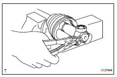
- Using a brass bar and hammer, tap out the tripod joint from the outboard joint shaft.
Notice:
Do not tap the rollers.
- Remove the inboard joint boot.
- Remove front drive shaft damper clamp lh
- One touch type:
- Using a screwdriver, remove the drive shaft damper clamp, as shown in the illustration.
- Claw engagement type:
Using needle-nose pliers, remove the drive shaft damper clamp, as shown in the illustration.
- Remove front drive shaft damper lh
- Remove the front drive shaft damper from the outboard joint shaft.
- Remove front axle outboard joint boot no. 2 Clamp lh
- Using a screwdriver, remove the outboard joint boot clamp, as shown in the illustration.
- Remove front axle outboard joint boot clamp lh
- Using a screwdriver, remove the outboard joint boot clamp, as shown in the illustration.
- Remove front axle outboard joint boot
- Remove the outboard joint boot from the outboard joint shaft.
- Remove any old grease from the outboard joint.
- Remove front drive shaft hole snap ring lh
- Using a screwdriver, remove the hole snap ring.
- Remove front drive shaft dust cover lh
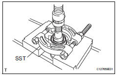
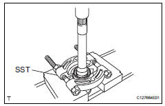
- Using sst and a press, press out the shaft dust cover
Sst 09950-00020
Notice:
Be careful not to drop the inboard joint
- Remove front drive shaft dust cover rh
Hint:
Use the same procedures described for the lh side.
- Remove drive shaft bearing case
- Using a screwdriver, remove the bearing case snap ring.
- Using a press, press out the drive shaft bearing case.
Hint:
Be careful not to drop the inboard joint
- Remove front drive shaft dust cover
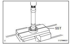
- Using sst and a press, press out the drive shaft dust cover.
Sst 09950-00020
Hint:
Be careful not to drop the inboard joint
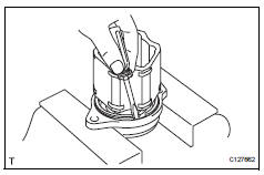
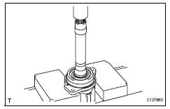
- Remove front drive shaft bearing
- Using a snap ring expander, remove the snap ring.
- Using sst and a press, press out the drive shaft bearing.
Sst 09527-10011
- Remove the snap ring.
 Removal
(2006/01- )
Removal
(2006/01- )
Remove front wheel
Drain automatic transaxle fluid
Drain the automatic transaxle fluid for u140f (see
page ax-147).
Drain the automatic transaxle fluid for u241e (see
page ax-146).
...
 Disassembly (2006/01- )
Remove front axle inboard joint boot no. 2 Clamp
One touch type:
using a screwdriver, remove the inboard joint boot
clamp, as shown in the illustration.
Claw engagement type:
usin ...
Other materials:
Cargo and luggage
Take notice of the following information about storage precautions,
cargo capacity and load:
Capacity and distribution
Cargo capacity depends on the total weight of the occupants.
(Cargo capacity) = (total load capacity) ƒ{ (total weight of occupants)
Steps for determining correct load l ...
Footwell light
On-vehicle inspection
Inspect footwell light
Connect the battery's positive (+) lead to terminal 2
and the negative (-) lead to terminal 1, then check
that the light comes on.
Ok:
light comes on.
If the result is not as specified, replace the light. ...
Shift position purpose
*1: Shifting the shift lever to d allows the system to select a gear suitable
for
the driving conditions.
Setting the shift lever to d is recommended for normal driving.
*2: Selecting shift ranges using s mode restricts the upper limit of the
possible
gear ranges, controls engine bra ...
