Toyota RAV4 (XA40) 2013-2018 Service Manual: Removal (2006/01- )
- Remove front wheel
- Drain automatic transaxle fluid
- Drain the automatic transaxle fluid for u140f (see page ax-147).
- Drain the automatic transaxle fluid for u241e (see page ax-146).
- Drain the automatic transaxle fluid for u151e (see page ax-172).
- Remove front axle hub nut (see page ah-8)
- Disconnect front speed sensor lh
- Disconnect the speed sensor (see page bc-191).
- Remove front speed sensor rh
Hint:
Use the same procedures described for the lh side.
- Disconnect front disc brake cylinder assembly lh (see page br-40)
- Disconnect front disc brake cylinder assembly rh
Hint:
Use the same procedures described for the lh side.
- Remove front stabilizer link assembly lh (see page sp-30)
- Remove front stabilizer link assembly rh
Hint:
Use the same procedures described for the lh side.
- Disconnect front suspension lower no. 1 Arm sub-assembly lh (see page sp-21)
- Disconnect front suspension lower no. 1 Arm sub-assembly rh
Hint:
Use the same procedures described for the lh side.
- Disconnect steering knuckle with axle hub lh
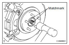
- Put matchmarks on the drive shaft and axle hub.
Notice:
Do not punch the marks.
- Using a plastic-faced hammer, disconnect the steering knuckle with axle hub.
Notice:
Be careful not to damage the boot and speed sensor rotor.
Do not excessively push out the drive shaft from the axle assembly.
- Disconnect steering knuckle with axle hub rh
Hint:
Use the same procedures described for the lh side.
- Disconnect tie rod end sub-assembly lh (see page ps-42)
- Disconnect tie rod end sub-assembly rh
Hint:
Use the same procedures described for the lh side.
- Remove front drive shaft assembly lh
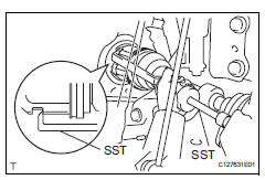
- Using sst, remove the front drive shaft.
Sst 09520-01010, 09520-24010 (09520-32040)
Notice:
- Be careful not to damage the transaxle case oil seal, inboard joint boot and drive shaft dust cover.
- Be careful not to drop the drive shaft.
- Remove front drive shaft assembly rh
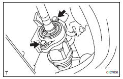
- Remove the 2 bolts and pull out the drive shaft together with the drive shaft bearing case
- Remove the drive shaft from the transaxle.
Notice:
- Be careful not to damage the transaxle case oil seal, inboard joint boot and drive shaft dust cover.
- Be careful not to drop the drive shaft.
- Fix front axle assembly
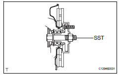
Notice:
The hub bearing could be damaged if it is subjected to the vehicle weight, such as when moving the vehicle with the drive shaft removed. Therefore, if it is absolutely necessary to place the vehicle weight on the hub bearing, first support it with sst.
Sst 09608-16042 (09608-02021, 09608-02041)
 Removal (2005/11-2006/01)
Remove front wheel
Drain automatic transaxle fluid
Drain the automatic transaxle fluid for u140f (see
page ax-147).
Drain the automatic transaxle fluid for u241e (see
page ax-146).
...
 Disassembly (2005/11-2006/01)
Remove front axle inboard joint boot no. 2 Clamp lh
One touch type:
Using a screwdriver, remove the inboard joint
boot clamp, as shown in the illustration.
Claw engagement t ...
Other materials:
Manual shifting test
Manual shifting test
Hint:
Through this test, it can be determined whether the
trouble occurs in the electrical circuit or if it is a
mechanical problem in the transaxle.
If any abnormalities are found in the following test, the
problem is in the transaxle itself.
Disconnect ...
4Wd control ecu communication stop mode
Description
Hint:
For vehicle with 4wd only.
Wiring diagram
Inspection procedure
Notice:
Turn the ignition switch off before measuring the resistances of the
main wire and the branch
wire.
After the ignition switch is turned off, check that the key reminder
warning system ...
General maintenance (2006/01- )
Inspect steering linkage and gear housing
Check the steering wheel free play.
Check the steering linkage for looseness or
damage.
Check that the tie rod ends do not have
excessive play.
Check that the dust seals and boots are not
damaged.
Check that the boot clamps are not ...
