Toyota RAV4 (XA40) 2013-2018 Service Manual: Door control transmitter module
Components
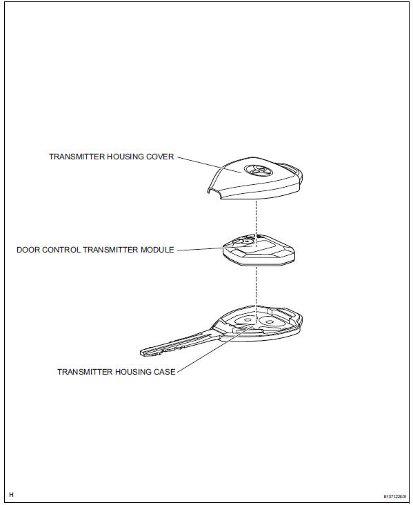
Removal
- Remove transmitter housing cover
Notice:
Take extra care when handling these precision electronic components.
- Twist the screwdriver in the direction of the arrow mark in the illustration, and open the transmitter housing cover.
Notice:
Do not forcibly pry the cover.
Hint:
Tape the screwdriver tip before use.
- Remove door control transmitter module
Inspection
- Inspect door control transmitter module
- Inspect operation of the transmitter.
- emove the battery (lithium battery: cr2016) from the transmitter.
- Install a new or non-depleted battery (lithium battery: cr2016).
Hint:
When a new or non-depleted battery is not available, first connect 2 new 1.5 V batteries in series. Then connect leads to the batteries and use the leads to apply 3 v to the transmitter, as shown in the illustration
- From outside the vehicle, approximately 1 m (3.28 Ft.) From the driver side outside door handle, test the transmitter by pointing its key plate at the vehicle and pressing a transmitter switch.
Ok: door lock can be operated via the transmitter. Led illuminates more than Once.
Hint:
- The operating range differs depending on the user, the way the transmitter is held and the location.
- The transmitter's faint electric waves may be affected if the area has strong electric waves or noise. The transmitter's operating range may be shortened or the transmitter may not function.
- Inspect the battery capacity.
Hint:
- When checking the amount of energy left in the battery, the battery must be checked while it is installed in the transmitter (a resistance of 1.2 Kù is applied to the battery). When the battery energy is checked by itself (uninstalled), the voltage reading will be more than 2.5 V until the energy is depleted.
- If the transmitter is malfunctioning, the voltage reading of the energy left in the battery will be inaccurate.
- Remove the battery from the transmitter.
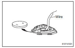
- Connect a wire to the negative (-) terminal of the transmitter and install the battery.
- Connect the tester's positive (+) lead to the battery and the negative (-) lead to the wire.
- Press one of the transmission switches on the transmitter for approximately 1 second.
- Press the transmission switch on the transmitter again to check the voltage.
Standard voltage: 2.2 V or higher
Hint:
- When the temperature of the battery is low,
the inspection result will not be accurate.
When the inspection result is less than 2.2 V, conduct the test again after leaving the battery in a place with a temperature of 18? (64?) for more than 30 minutes.
- Read the voltage immediately after the
switch is pressed. When 0.8 Seconds have
passed after the switch is pressed, the
automatic power off function starts and
resistance applied to the battery will cease.
The voltage of the battery will be 2.5 V or more.
- Press the switch at least 3 times before reading the voltage. If the battery temperature has just returned to 18? (64?), the voltage may be unusually high for the first or second voltage reading.
Installation
- Install door control transmitter module
Notice:
Take extra care when handling these precision electronic components.
- Install transmitter housing cover
- Install the transmitter housing cover to the transmitter housing case.
- Check that the transmitter's led illuminates 3 times when the switch is pressed 3 times.
Ok: transmitter's led illuminates 3 times when switch is pressed 3 times.
 Data list / active test
Read data list
Hint:
Using the intelligent tester's data list allows switch,
actuator and other item values to be read without
removing any parts. Reading the data list early in
troubleshoot ...
 Door control switch
Inspection
Inspect power window regulator master
switch assembly (door control switch)
Measure the resistance of the door control switch.
Standard resistance
If the result is not ...
Other materials:
Problem symptoms table (2006/01- )
Hint:
Use the table below to help determine the cause of the
problem symptom. The potential causes of the symptoms are
listed in order of probability in the "suspected area" column
of the table. Check each symptom by checking the suspected
areas in the order they are listed. Replace p ...
Parking brake
The parking brake can be
set or released automatically
or manually.
In automatic mode, the
parking brake can be set or
released automatically
according to shift lever
operation. Also, even in
automatic mode, the parking
brake can be set or
released manually.
Operating instructions
â– Using the man ...
Radiator
Components
On-vehicle inspection
Check radiator reservoir cap subassembly
Measure the valve opening pressure.
If there are water stains or foreign matter on oring
1, clean it with water and finger scouring.
Check that o-ring 1 is not deformed, cracked or
sw ...
