Toyota RAV4 (XA40) 2013-2018 Service Manual: Driver side seat belt warning light does not operate
Description
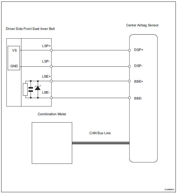
When the ignition switch is on, the center airbag sensor transmits front seat inner belt status signals to the combination meter through the can bus line. If the driver seat belt is not fastened, the combination meter blinks the driver side seat belt warning light. If the seat belt is fastened, the warning light goes off.
Notice:
The seat belt warning system uses the can bus line. Before troubleshooting the seat belt warning system, perform "communication function check" by following "how to proceed with troubleshooting" to confirm that the communication systems are normal.
Wiring diagram
Inspection procedure
- Perform active test using intelligent tester
- Select the active test, use the intelligent tester to generate a control command, and then check that the seat belt warning light operates.
Center airbag sensor:

Ok: driver side seat belt warning light operates normally.

Replace center airbag sensor assembly
 On-vehicle inspection
Check driver side seat belt warning light
Turn the ignition switch on.
When the driver side seat belt is not fastened, check
that the combination meter's driver side seat belt
warning l ...
 Front passenger side seat belt warning light malfunction
Description
When the ignition switch is on, the center airbag sensor transmits front seat
inner belt status signals to
the combination meter through the can bus line. If the front passenger seat b ...
Other materials:
Removal
Caution:
Be sure to read the precautionary notices concerning the
srs airbag system before servicing it (see page rs-1).
Disconnect cable from negative battery
terminal
Caution:
Wait at least 90 seconds after disconnecting the
cable from the negative (-) battery terminal to
prevent air ...
Low battery positive voltage
Description
When there is an abnormality in the power supply circuit of the brake
actuator (skid control ecu), the skid
control ecu sets a dtc and the operation is prohibited by the fail-safe
function. This dtc is set when the
voltage supplied to terminal ig1 is outside the dtc detection ...
Seat position sensor
Components
On-vehicle inspection
Check seat position sensor (vehicle not
involved in collision)
Perform a diagnostic system check (see page rs-
49).
Check seat position sensor (vehicle
involved in collision)
Perform a diagnostic system check (see page rs-
49).
Ev ...
