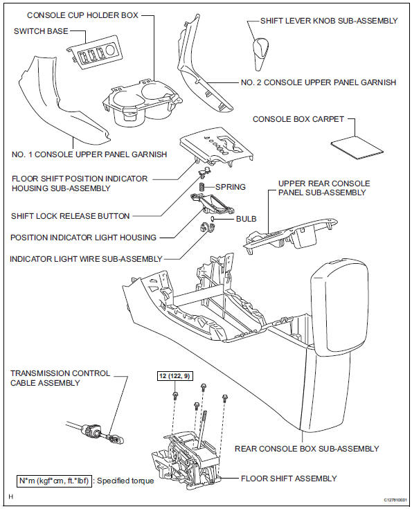
Toyota RAV4 (XA40) 2013-2018 Service Manual: Floor shift assembly
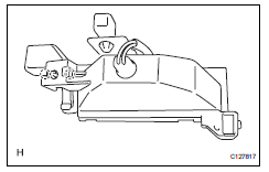
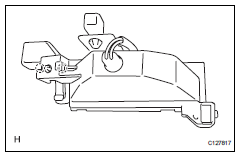
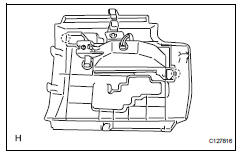
Components
Removal
- Disconnect cable from negative battery terminal
Caution:
Wait at least 90 seconds after disconnecting the cable from the negative (-) battery terminal to prevent airbag and seat belt pretensioner activation.
- Remove shift lever knob sub-assembly
- Remove rear console box sub-assembly
- Remove the console box (see page ip-20).
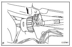
- Disconnect transaxle control cable assembly
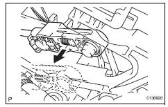
- disconnect the control cable from the shift lever.
- Turn the nut and disconnect the control cable from the shift lever retainer.
- Remove floor shift assembly
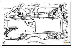
- Remove the 4 bolts and floor shift.
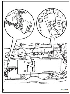
- Disconnect the 2 connectors and detach the clamp.
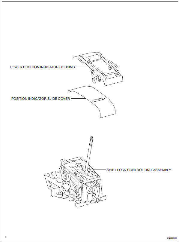
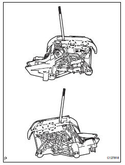
Disassembly
- Remove lower position indicator housing
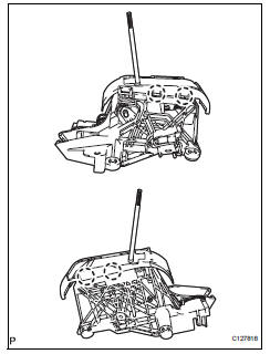
- Detach the 4 claws and remove the housing.
- Remove the position indicator slide cover with slide no. 2 Cover.
- Remove position indicator light housing
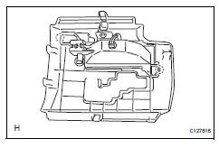
- Detach the 2 claws and remove the indicator light housing from the floor shift position indicator housing.
- Remove indicator light wire sub-assembly
- Remove shift lock release button
- Detach the 2 claws and remove the button and spring from the position indicator light housing.
Adjustment
- Inspect shift lever position
- When shifting the lever from p to the r position with the ignition switch on and the brake pedal depressed, make sure that the shift lever moves smoothly and moves correctly into position.
- Start the engine and make sure that the vehicle
moves forward when shifting the lever from n to the
d position and moves rearward when shifting the
lever to the r position.
If the operation cannot be performed as specified, inspect the park/neutral position switch assembly and check the shift lever assembly installation condition.
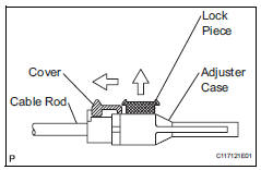
- Adjust shift lever position
- Shift the shift lever to the n position.
- Slide the adjuster case cover in the direction shown in the illustration and pull out the lock piece.
- Gently pull the cable rod toward the rear of the vehicle by hand to pull the cable taut.
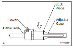
- Press the lock piece into the adjuster case and lock it.
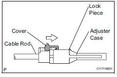
- Slide the cover in the direction shown in the illustration.
Notice:
Slide the cover past the protrusion of the lock piece.
- Inspect the operation after the adjustment.
Reassembly
- Install shift lock release button
- Install the spring and button and attach the claws to the position indicator light housing.
- Install indicator light wire sub-assembly
- Install position indicator light housing
- Attach the indicator light housing to the shift position indicator housing with the 2 claws.
- Install lower position indicator housing
- Install the position indicator slide cover with slide cover no. 2 To the indicator housing.
- Attach the housing to the floor shift assembly with the 4 claws.
Installation
- Install floor shift assembly
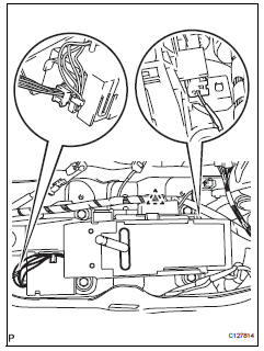
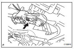
- Connect the 2 connectors and attach the clamp.
- Install the floor shift with the 4 bolts.
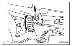
- Connect transaxle control cable assembly
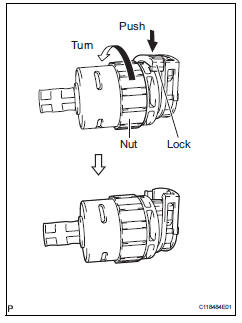
- turn the nut of the control cable and push in the lock.
- Install the control cable onto the shift lever retainer.
Notice:
Install the cable with the protruding portion of the cable outer facing upward.
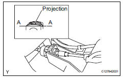
- After installing, check that the lock of the cable outer is protruding beyond portion a-a, as shown in the illustration.
- Connect the control cable to the shift lever.
Notice:
Connect the control cable so that the adjusting mechanism lock of the control cable is installed on the driver side of the vehicle.
- Connect cable to negative battery terminal
- Inspect shift lever position (see page ax-138)
- Adjust shift lever position (see page ax-138)
- Install rear console box sub-assembly
- Install the rear console box (see page ip-26).
- Install shift lever knob sub-assembly
 Transmission control cable assembly
Replacement
Remove rear console box sub-assembly
Remove the console box (see page ip-20).
Disconnect cable from negative battery
terminal
Caution:
Wait at least 90 seconds after ...
 Differential oil seal
Components
Replacement
Replace transaxle housing oil seal lh
Drain the automatic transaxle fluid.
Remove the drain plug and gasket, and drain
atf.
Install a new gasket and ...
Other materials:
Air-fuel ratio (a/f) and heated oxygen (ho2) sensor
heater monitors (front a/f and rear ho2 sensor type)
Preconditions
The monitor will not run unless:
The mil is off.
Drive pattern
Connect the intelligent tester to the dlc3.
Turn the ignition switch on.
Turn the tester on.
Clear dtcs (if set) (see page es-35).
Start the engine.
Allow the engine to idle for 10 minute ...
Rear window wiper
and washer
Turning the end of the lever turns on the rear window wiper, and pushing
the lever away from you turns on the rear window wiper and
washer.
For the u.S.A.
Intermittent operation
Normal operation
Washer/wiper dual operation
For Canada
Intermittent operation
Normal oper ...
Console box
Lift the lid while pulling up the
lever to release the lock.
When using the console box lid as an armrest (vehicles with slide
function)
Slide the console box lid forward as
needed. Pull the lid forward by holding the
front of the lid.
Caution
Console box adjustment precaution
D ...
