Toyota RAV4 (XA40) 2013-2018 Service Manual: Control module communication bus off
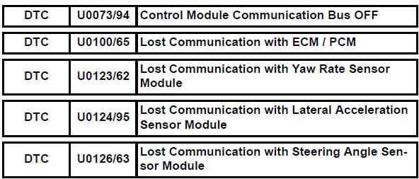
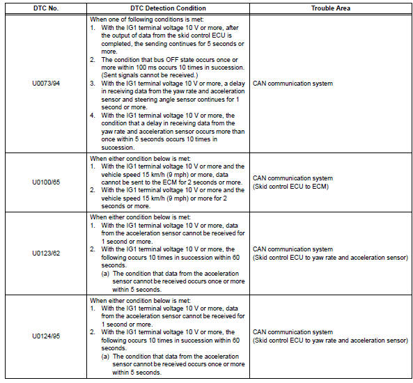
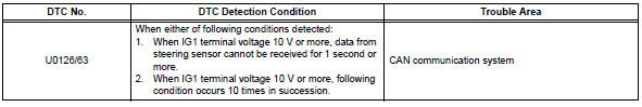
Description
Inspection procedure
The skid control ecu inputs the signals from the ecm, steering angle sensor, and yaw rate and acceleration sensor via can communication system.
- Check harness and connector (momentary interruption)
- Using the data list of the intelligent tester, check for any momentary interruption in the wire harness and connector corresponding to a dtc (see page bc-23).
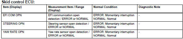
Result 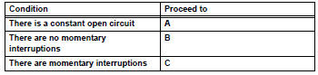
Hint:
Perform the above inspection before removing the sensor and connector.

- Check if each sensor and ecm connector is securely connected
- Check if each sensor or ecm connector is securely connected.
Ok: the connector should be securely connected.

- Reconfirm dtc
- Record the output dtcs (for abs, vsc and can communication) (see page bc-47).
Hint:
If the can communication system dtc and the relevant sensor dtcs are output simultaneously, troubleshoot the relevant sensor dtcs (for abs and vsc) after the can communication system returns to normal.
Result 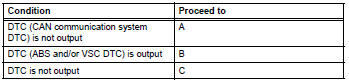

Inspect can communication system
- Repair or replace harness and connector
- Repair or replace the harness or connector.
- Check for any momentary interruption between the skid control ecu and each sensor or ecm (see page bc-23).
- Check that there is no momentary interruption.

- Reconfirm dtc
- Clear the dtc (see page bc-47).
- Turn the ignition switch on.
- Drive the vehicle and turn the steering wheel to the right and left at a speed of 15 km/h (9 mph) or more.
- Check that no can communication system dtc is output (see page bc-47).
- If abs and/or vsc dtcs are output, record them.
Result 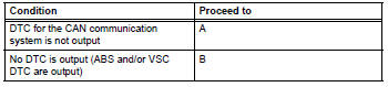
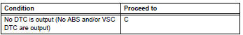
Hint:
The can communication system must be normal when repairing the sensor dtcs (for abs and vsc).

Inspect can communication system
 Downhill assist control operation switch (test mode dtc)
Description
The downhill assist control switch is connected to the skid control ecu in
the abs and traction
actuator.
Dtc c1379/74 can be detected when the downhill assist control switch se ...
 Abs warning light remains on
Description
If any of the following conditions are detected, the abs warning light
remains on:
The ecu connectors are disconnected from the skid control ecu.
There is a malfunction in the ski ...
Other materials:
Child restraint system
â– Types of child restraint system installation methods
Confirm with the operation manual enclosed with the child restraint
system about the installation of the child restraint system.
Seat belt attachment
Child restraint LATCH
anchors attachment
Anchor brackets (for
top tether strap) attachment
...
Clock
The clock can be adjusted by pressing the buttons.
Adjusts the hours.
Adjusts the minutes.
The clock is displayed when
Vehicles without a smart key system
The engine switch is in the “acc” or “on” position.
Vehicles with a smart key system
The engine switch is in a ...
If your vehicle overheats
The following may indicate
that your vehicle is overheating.
The engine coolant temperature
gauge shows the red zone or a
loss of engine power is
experienced. (For example,
the vehicle speed does not
increase.)
"Engine Coolant Temp High
Stop in a Safe Place See
Owner's Manual" is shown
on ...
