Toyota RAV4 (XA40) 2013-2018 Service Manual: Abs warning light remains on
Description
If any of the following conditions are detected, the abs warning light remains on:
- The ecu connectors are disconnected from the skid control ecu.
- There is a malfunction in the skid control ecu internal circuit.
- There is an open or short in the wire harness between the combination meter and the skid control ecu.
Hint:
The intelligent tester may not be used when there is a malfunction in the skid control ecu.
Wiring diagram
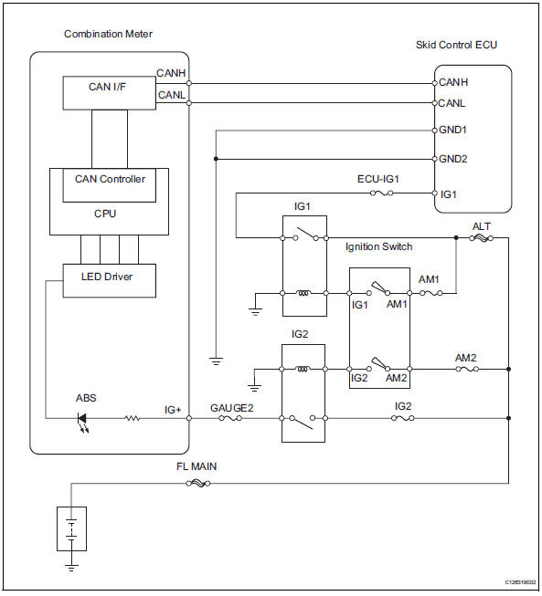
Inspection procedure
- Check can communication system
- Check if the can communication system dtc is output (see page ca-34).
Result 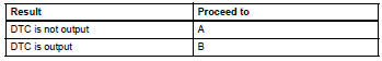

- Inspect skid control ecu connector
- Check if the skid control ecu connector is properly installed.
Ok: the skid control ecu connector is properly installed.

- Check wire harness (skid control ecu - battery and body ground)
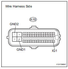
- Disconnect the a19 ecu connector.
- Measure the resistance of the wire harness side connector.
Standard resistance 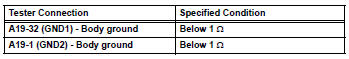
- Measure the voltage of the wire harness side connector.
Standard voltage 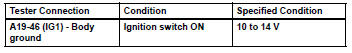

- Perform active test by intelligent tester (abs warning light)
- Select the active test, generate a control command, and then check that the abs warning light operates.

Ok: the abs warning light is turned on or off.
Hint:
When the abs warning light remains illuminated, opens in the wire harness of the combination meters or abnormalities in the meter circuit should be considered.

Replace abs and traction actuator assembly
 Control module communication bus off
Description
Inspection procedure
The skid control ecu inputs the signals from the ecm, steering angle sensor,
and yaw rate and
acceleration sensor via can communication system.
Ch ...
 Abs warning light does not come on
Wiring diagram
Refer to the abs warning light circuit (see page bc-135).
Inspection procedure
Check can communication system
Check if the can communication system dtc is output
(see page ...
Other materials:
Cargo and luggage
Take notice of the following information about storage precautions,
cargo capacity and load:
Capacity and distribution
Cargo capacity depends on the total weight of the occupants.
(Cargo capacity) = (total load capacity) ƒ{ (total weight of occupants)
Steps for determining correct load l ...
Diagnosis system
Check dlc3
The ecm uses iso 15765-4 for communication. The
terminal arrangement of the dlc3 complies with sae
j1962 and matches the iso 15765-4 format.
If the result is not as specified, the dlc3 may have a
malfunction. Repair or replace the harness and
connector.
Hint:
Conn ...
Front suspension lower no. 1 Arm
Components
Removal
Remove front wheel
Remove hood sub-assembly
Remove the hood (see page ed-4).
Suspend engine assembly
Install the no. 1 And no. 2 Engine hangers with the
bolts as shown in the illustration.
Torque: 38 n*m (387 kgf*cm, 28 ft.*Lbf)
parts no.
...
