Toyota RAV4 (XA40) 2013-2018 Service Manual: Downhill assist control operation switch (test mode dtc)

Description
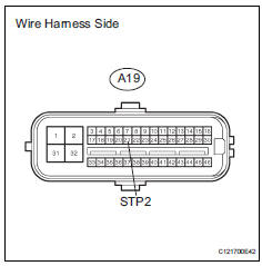
The downhill assist control switch is connected to the skid control ecu in the abs and traction actuator.
Dtc c1379/74 can be detected when the downhill assist control switch sends the downhill assist control switch signal or test mode ends. Dtc c1379/74 is output only in test mode.
![]()
Wiring diagram
Refer to downhill assist control switch circuit (see page bc-157).
Inspection procedure
Notice:
When replacing the abs and traction actuator, perform zero point calibration (see page bc-24).
- Check wire harness (skid control ecu - body ground)
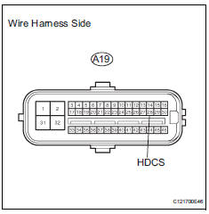
- Disconnect the a19 ecu.
- Measure the resistance of the wire harness side connector.
Standard resistance 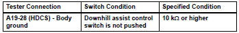

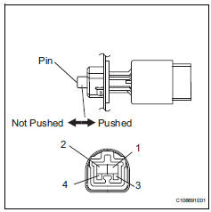
- Inspect downhill assist control switch
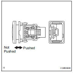
- Remove the downhill assist control switch.
- Measure the resistance of the switch.
Standard resistance 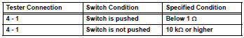

- Check wire harness (skid control ecu - downhill assist control switch)
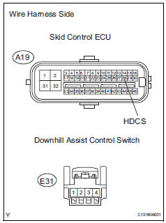
- Disconnect the a19 ecu connector.
- Disconnect the e31 switch connector.
- Measure the resistance of the wire harness side connectors.
Standard resistance 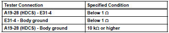

Replace abs and traction actuator assembly
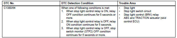
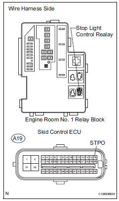
Stop light control relay malfunction
![]()
Description
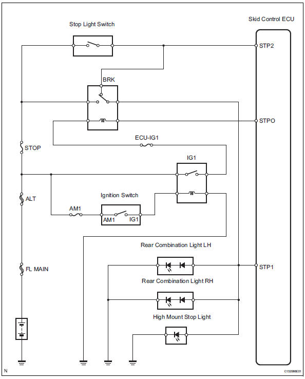
The skid control ecu inputs the stop light switch signal and detects the status of the brake operation.
Wiring diagram
Inspection procedure
Notice:
When replacing the abs and traction actuator, perform zero point calibration (see page bc-24).
- Check stop light (operation)
- Check that the light illuminates when the brake pedal is depressed, and turns off when the brake pedal is released.
Ok 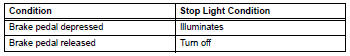

- Check wire harness (skid control ecu - battery)
- Disconnect the a19 ecu connector.
- Measure the voltage of the wire harness side connector.
Standard voltage 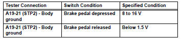

- Check wire harness (skid control ecu)
- Disconnect the a19 ecu connector.
- Measure the resistance of the wire harness side connector
Standard resistance 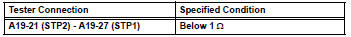

- Perform active test by intelligent tester (stop light relay)
- Select the active test, generate a control command, and then check that the stop light relay operates.

Ok: the stop lights illuminate or turn off.

- Reconfirm dtc
- Clear the dtc (see page bc-47).
- Start the engine.
- Drive the vehicle at a speed of 5 km/h (3 mph) or more for several seconds.
- Check if the same dtc is output (see page bc-47).
Result 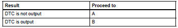


Replace abs and traction actuator assembly
- Inspect stop light control relay (marking: brk)
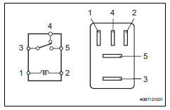
- Remove the stop light control relay from the engine room no. 1 Relay block.
- Measure the resistance of the relay.
Standard resistance 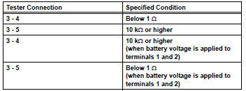

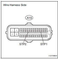
- Check wire harness (engine room no. 1 Relay block - skid control ecu and battery)
- Remove the stop light control relay.
- Disconnect the a19 ecu connector.
- Measure the voltage of the wire harness side connector.
Standard voltage 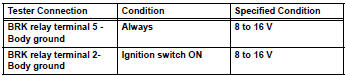
- Measure the resistance of the wire harness side connector.
Standard resistance 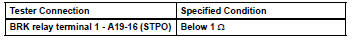

- Reconfirm dtc
- Clear the dtc (see page bc-47).
- Start the engine.
- Drive the vehicle at a speed of 5 km/h (3 mph) or more for several seconds.
- Check if the same dtc is output (see page bc-47).
Result 


Replace abs and traction actuator assembly
- Check wire harness (stop light switch - battery)
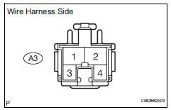
- Disconnect the a3 switch connector.
- Measure the voltage of the wire harness side connector.
Standard voltage 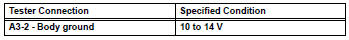

- Inspect stop light switch assembly
- Remove the stop light switch connector.
- Measure the resistance of the switch.
Standard resistance 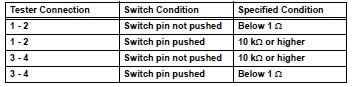

- Check wire harness (stop light switch - stop light control relay)
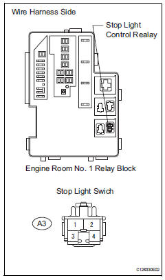
- Disconnect the a3 switch connector.
- Remove the stop light control relay.
- Measure the resistance of the wire harness side connectors.
Standard resistance 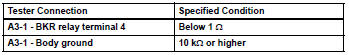

- Inspect stop light control relay (marking: brk)
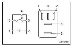
- Remove the stop light control relay from the engine room no. 1 Relay block.
- Measure the resistance of the relay.
Standard resistance 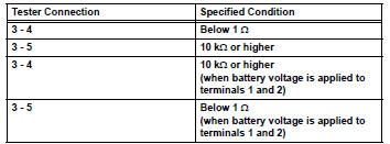

- Check wire harness (stop light and rear combination light - control relay)
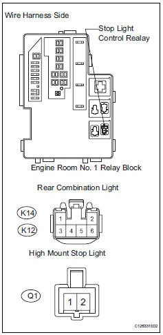
- Disconnect the q1, k12 and k14 light connectors.
- Remove the stop light control relay.
- Measure the resistance of the wire harness side connectors.
Standard resistance 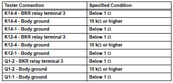

Check for intermittent problems
 Different diameter tire malfunction
Description
The skid control ecu measures the speed of each wheel by receiving signals
from the speed sensor.
These signals are used for recognizing that all 4 wheels are operating properly. ...
 Control module communication bus off
Description
Inspection procedure
The skid control ecu inputs the signals from the ecm, steering angle sensor,
and yaw rate and
acceleration sensor via can communication system.
Ch ...
Other materials:
Precaution
Precaution for vehicle with srs airbag and
seat belt pretensioner
Some operations in this section may affect the srs
airbags and seat belt pretensioner. Prior to
performing the corresponding operations, read the
srs airbag notice (see page rs-1).
Components
...
Yaw rate and deceleration sensor
Components
Removal
Disconnect cable from negative battery
terminal
Caution:
Wait at least 90 seconds after disconnecting the
cable from the negative (-) battery terminal to
prevent airbag and seat belt pretensioner activation.
Remove front seat assembly lh
For manual seat: ...
Installation
Hint:
Use the same procedures for the rh side and lh side.
The procedures listed below are for the lh side.
Install no. 2 Seat leg box protector
Attach the clip to install the protector.
Install the clip.
Install rear no. 1 Floor mat support side plate
Install rear no ...
