Toyota RAV4 (XA40) 2013-2018 Service Manual: Different diameter tire malfunction
![]()
Description
The skid control ecu measures the speed of each wheel by receiving signals from the speed sensor.
These signals are used for recognizing that all 4 wheels are operating properly. Therefore, all wheel signals must be equal.
Inspection procedure
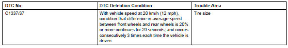
- Check tire size
- Check the diameter of all 4 tires.
Ok: diameter of all 4 tires are equal.

- Check speed sensor rotor
- Remove the drive shaft, and check around the speed sensor rotor.
Ok: no scratches or foreign matter on the sensor tip.


- Check speed sensor


- Check the speed sensor circuit (see page bc-64 or bc- 70).
- Check wire harness (skid control ecu - each speed sensor)
- Check the speed sensor circuit (see page bc-69 or bc- 70).

- Reconfirm dtc
- Clear the dtcs (see page bc-47).
- Drive the vehicle at more than 20 km/h (12 mph) for more than 60 seconds.
- Check if the same dtcs are detected.
Result 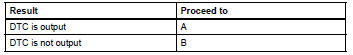


Replace abs and traction actuator assembly
 Steering angle sensor zero point malfunction
Description
The skid control ecu learns the steering sensor zero point every time the
ignition switch is turned on and
the vehicle is driven at 35 km/h (22 mph) or more for approximately 5 sec ...
 Downhill assist control operation switch (test mode dtc)
Description
The downhill assist control switch is connected to the skid control ecu in
the abs and traction
actuator.
Dtc c1379/74 can be detected when the downhill assist control switch se ...
Other materials:
Components (2005/11-2006/01)
Sliding roof ecu power source circuit
Description
If the sliding function and tilt function do not operate, there may be a
malfunction in the sliding roof ecu
power source circuit.
Wiring diagram
Inspection procedure
Perform active test by i ...
Components
(2005/11-2006/01)
...
Optimal use of the
audio system
On the ÔÇťsound settingsÔÇŁ screen, sound quality (treble/mid/
bass), volume balance can be adjusted.
How to adjust the sound settings and sound quality
Select ÔÇť-ÔÇŁ or ÔÇť+ÔÇŁ to adjust
the treble, mid or bass to
a level between -5 and 5.
Select ÔÇťfrontÔÇŁ or ÔÇťrearÔÇŁ to
adjust the fr ...
