Toyota RAV4 (XA40) 2013-2018 Service Manual: Removal
Hint:
- Use the same procedures for the rh side and lh side.
- The procedures listed below are for the lh side.
- When removing the moulding, heat the vehicle body and moulding using a heat light.
Standard heating temperature 
Notice:
Do not heat the vehicle body and moulding excessively.
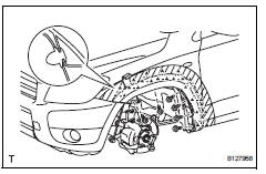
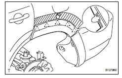
- Remove front fender moulding subassembly lh
- Put protective tape around the moulding.
- Remove the 4 screws and detach the 2 clips.
- Using a moulding remover, detach the 9 clips and remove the moulding.
Notice:
- If reusing the moulding, take care not to damage the moulding.
- Be careful not to damage the vehicle body.
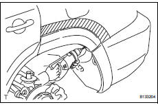
- Remove no. 2 Rear wheel opening extension lh
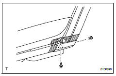
- Put protective tape around the moulding.
- Remove the screw.
- Using a clip remover, detach the 2 clips and remove the extension.
Notice:
- If reusing the extension, take care not to damage the extension.
- Be careful not to damage the vehicle body.
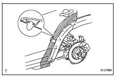
- Remove no. 1 Rear wheel opening extension lh
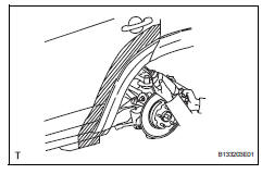
- Put protective tape around the extension.
- Using a drill bit of less than ö 4 mm (0.16 In.), Drill out the 3 rivet flanges.
Hint:
Wind tape around the drill bit approximately 5 mm (0.20 In.) From the tip of the drill.
Notice:
- Do not drill the rivet at an angle as this will cause damage to the drill and drill hole. Line up the drill and rivet, and carefully drill out the rivet head.
- Be careful as the cut rivet will be very hot.
- Continue drilling and push out the remaining rivet fragments using the drill.
- Using a vacuum cleaner, remove the rivet fragments and shavings from the drilled areas.
- Using a heat light, heat the extension and vehicle body.
- Cut the double-sided tape that holds the moulding to the vehicle body with a knife.
Notice:
- If reusing the extension, take care not to damage the extension.
- Be careful not to damage the vehicle body.
- Using a moulding remover, detach the 5 clips and remove the extension.
- Remove rear quarter outside moulding lh
- Put protective tape around the moulding.
- Using a drill bit of less than ö 4 mm (0.16 In.), Drill out the 3 rivet flanges.
Hint:
Wind tape around the drill bit approximately 5 mm (0.20 In.) From the tip of the drill.
Notice:
- Do not drill the rivet at an angle as this will cause damage to the drill and drill hole. Line up the drill and rivet, and carefully drill out the rivet head.
- Be careful as the cut rivet will be very hot.
- Continue drilling and push out the remaining rivet fragments using the drill.
- Using a vacuum cleaner, remove the rivet fragments and shavings from the drilled areas.
- Using a heat light, heat the moulding and vehicle body.
- Using a moulding remover, detach the 5 clips and remove the moulding.
Notice:
- If reusing the moulding, take care not to damage the moulding.
- Be careful not to damage the vehicle body.
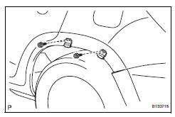
- Remove no. 2 Rocker panel moulding retainer lh
- Remove the 2 screws and retainer.
- Remove quarter opening retainer lh
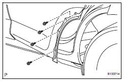
- Remove the 4 screws and retainer.
- Remove no. 1 Rocker panel moulding retainer lh
- Remove the 4 screws and 2 retainers.
 Outside moulding
Components
...
 Installation
Hint:
Use the same procedures for the rh side and lh side.
The procedures listed below are for the lh side.
When installing the moulding, heat the vehicle body and
moulding using a heat ligh ...
Other materials:
Fuel consumption information
The fuel consumption information can be displayed on entune
premium audio with navigation and entune audio screen.
Display the trip information or past record screen
Vehicles with entune audio
Press the “car” button.
Vehicles with entune premium audio with navigation and entune
au ...
Removal
Hint:
When removing the spoiler, heat the vehicle body and spoiler
using a heat light.
Standard heating temperature
Notice:
Do not heat the vehicle body and spoiler excessively.
Disconnect cable from negative battery
terminal
Caution:
Wait at least 90 seconds after disconnecting the
...
Push switch / key unlock warning switch malfunction
Description
This dtc is output if the transponder key ecu does not detect that the unlock
warning switch is on even
when the ignition switch is on. Under normal conditions, the unlock warning
switch is on when the
ignition switch is on.
Wiring diagram
Inspection procedure
Re ...
