Toyota RAV4 (XA40) 2013-2018 Service Manual: Yaw rate and deceleration sensor
Components
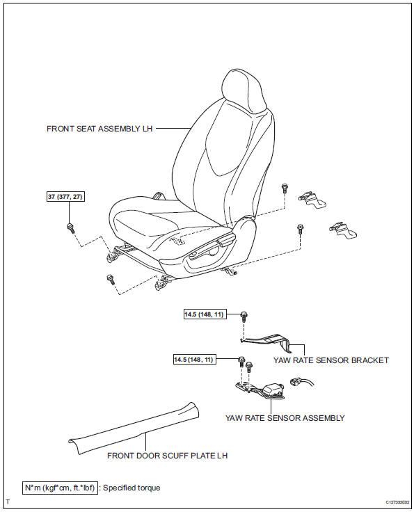
Removal
- Disconnect cable from negative battery terminal
Caution:
Wait at least 90 seconds after disconnecting the cable from the negative (-) battery terminal to prevent airbag and seat belt pretensioner activation.
- Remove front seat assembly lh
- For manual seat: remove the front seat lh (see page se-11).
- For power seat: remove the front seat lh (see page se-27).
- Remove front door scuff plate lh (see page ir-26)
- Remove yaw rate sensor bracket
- Remove the bolt and yaw rate sensor bracket.
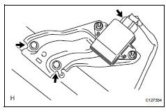
- Remove yaw rate sensor assembly
- Disconnect the yaw rate sensor connector.
- Remove the 2 bolts and yaw rate sensor.
Notice:
Do not remove the sensor from the bracket.
Inspection
- Inspect yaw rate sensor
- Inspect the yaw rate sensor. If any of the following occurs, replace the yaw rate sensor with a new one.
- The surface of the sensor is cracked, dented, or chipped.
- The connector or wire harness is scratched, cracked, or damaged.
- The sensor has been dropped.
Installation
- Install yaw rate sensor assembly
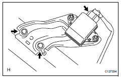
- Install the yaw rate sensor with the 2 bolts.
Torque: 14.5 N*m (148 kgf*cm, 11 ft.*Lbf)
Notice:
- Do not damage the yaw rate sensor.
- Make sure that the yaw rate sensor is installed securely.
- Connect the yaw rate sensor connector.
- Install yaw rate sensor bracket
- Install the bracket with the bolt.
Torque: 14.5 N*m (148 kgf*cm, 11 ft.*Lbf)
- Install front door scuff plate lh (see page ir-59)
- Install front seat assembly lh
- For manual seat: install the front seat (see page se-22).
- For power seat: install the front seat (see page se-37).
- Connect cable to negative battery terminal
- Perform zero point calibration of yaw rate and deceleration sensor
- Perform the yaw rate and deceleration sensor zero point calibration (see page bc-24).
- Inspect yaw rate sensor signal
- Inspect the yaw rate sensor signal (see page bc- 28).
 Rear speed sensor (for 4wd)
Components
Removal
Hint:
Use the same procedures for the lh side and rh side.
The procedures listed below are for the lh side.
Disconnect cable from negative battery
terminal
Ca ...
 Steering angle sensor
Components
Removal
Precaution
Caution:
Be sure to read the "precaution" thoroughly
before servicing (see page rs-1).
Disconnect cable from negative battery
terminal
Ca ...
Other materials:
Horn relay
On-vehicle inspection
Remove engine room no. 1 Relay block cover
Inspect integration relay (unit a: horn relay)
Using a screwdriver, detach the 2 claws and
disconnect the integration relay from the engine
room junction block.
Hint:
Tape the screwdriver tip before use.
Mea ...
Multiplex communication circuit
Description
The air conditioning amplifier communicates data with the ecm and combination
meter through the can
communication system.
Wiring diagram
Inspection procedure
Check dtc
Clear the dtc (see page ac-31).
Read the dtc (see page ac-31).
Result
Go to can c ...
How to proceed with troubleshooting
Hint:
Use these procedures to troubleshoot the tire pressure
warning system.
*: Use the intelligent tester.
Vehicle brought to workshop
Inspect battery voltage
Standard voltage:
11 to 14 v
If the voltage is below 11 v, recharge or replace the battery
before proceeding.
...
