
Toyota RAV4 (XA40) 2013-2018 Service Manual: Fuel pressure regulator
Components
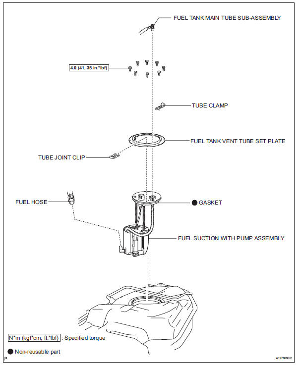
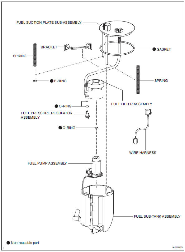
Removal
- Remove fuel tank assembly
- Remove the fuel tank (see page fu-39).
- Remove fuel tank main tube sub-assembly
- Remove the joint clip and fuel tank main tube.
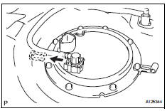
Caution:
- Before removing the tube joint clip, check for foreign matter around the clip. Clean if necessary.
- Keep the o-ring free of foreign matter, as it becomes contaminated easily.
- Do not use any tools in this procedure.
- Do not forcefully bend or twist the tube.
- Put the tube in a plastic bag to prevent damage and contamination.
- If the fuel suction plate and tube are stuck together, pinch the tube and turn it carefully to disconnect it.
- Be careful not to damage the clip. If the clip is damaged, replace it.
- Remove fuel tank vent tube set plate
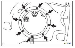
- Remove the 8 bolts and set plate.
- Remove fuel suction with pump assembly
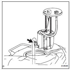
- Disconnect the fuel hose and remove the fuel pump from the fuel tank.
Notice:
Do not damage the fuel pump.
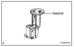
- Remove the gasket from the fuel pump.
- Remove fuel sub-tank assembly
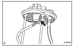
- Disconnect the wire harness.
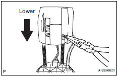
- Using needle nose pliers, remove the e-ring.
Hint:
Slightly lower the sub-tank to remove the e-ring.
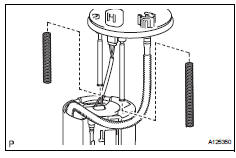
- Remove the 2 springs from the 2 shaft.
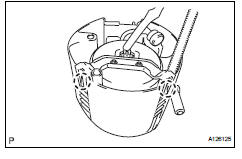
- Detach the 2 claws and remove the sub-tank.
- Remove bracket
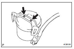
- Using a screwdriver, detach the 2 claws and remove the bracket.
Hint:
Tape the screwdriver tip before use.
- Remove fuel pump assembly
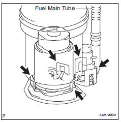
- Detach the 5 claws on the filter and remove the fuel pump from the fuel filter.
Hint:
When removing the claw, do not disconnect the fuel main tube.
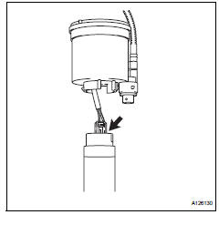
- Disconnect the fuel pump connector.
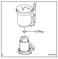
- Remove the o-ring from the fuel filter.
- Remove fuel pressure regulator assembly
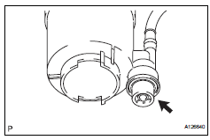
- Remove the fuel pressure regulator from the fuel filter.
- Remove the 2 o-rings.
Installation
- Install fuel pressure regulator assembly
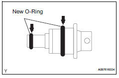
- Apply a light coat of gasoline to 2 new o-rings, and install them onto the fuel pressure regulator.
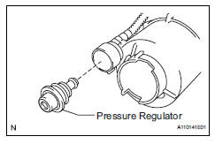
- Install the fuel pressure regulator to the fuel filter.
- Install fuel pump assembly
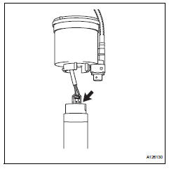
- Connect the pump harness connector.
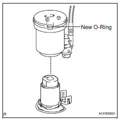
- Apply gasoline to a new o-ring and install the o-ring to the fuel filter.
- Attach the 5 claws to the claw holes and install the fuel pump.
- Install bracket
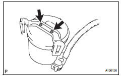
- Attach the 2 claws to the claw holes and install the bracket.
- Install fuel sub-tank assembly
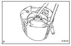
- Attach the 2 claws to the claw holes and install the fuel sub-tank.
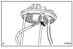
- Connect the wire harness.
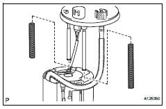
- Install the spring to the fuel suction plate shaft and install it to the sub-tank.
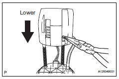
- Using needle-nose pliers, install a new e-ring.
Hint:
Slightly lower the sub-tank to install the e-ring.
- Install fuel suction with pump assembly
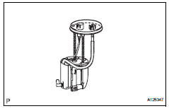
- Install a new gasket onto the fuel pump.
- Connect the fuel hose and install the fuel pump into the fuel tank.
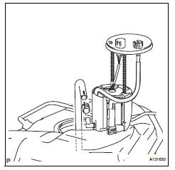
Notice:
Do not damage the fuel pump filter.
- Install fuel tank vent tube set plate
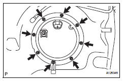
- Install the set plate with the 8 bolts.
Torque: 4.0 N*m (41 kgf*cm, 35 in.*Lbf)
- Install fuel tank main tube sub-assembly
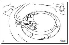
- Install the fuel tube with the joint clips.
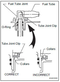
Caution:
- Check that there are no scratches or foreign objects on the connecting parts.
- Check that the fuel tube joint is inserted securely.
- Check that the fuel tube joint clip is on the collars of the fuel tube joint.
- After installing the tube joint clip, check that the fuel tube joint has not been pulled off.
- Be careful not to damage the clip. If the clip is damaged, replace it.
- Install fuel tank assembly
- Install the fuel tank (see page fu-44).
 Fuel injector
Components
Removal
Discharge fuel system pressure
Caution:
Discharge fuel system pressure
procedures must be performed before
disconnecting any part of the fuel system.
After ...
 Fuel pressure pulsation damper
Components
Removal
Discharge fuel system pressure (see page
fu-9)
Disconnect cable from negative battery
terminal
Remove no. 1 Engine cover (see page es-410)
Remove air cleaner ...
Other materials:
Check mode procedure
Description
Check mode has a higher sensitivity to malfunctions
and can detect malfunctions that normal mode
cannot detect. Check mode can also detect all the
malfunctions that normal mode can detect. In check
mode, dtcs are detected with 1 trip detection logic.
Check mode pro ...
General maintenance (2005/11-2006/01)
Inspect steering linkage and gear housing
Check the steering wheel free play.
Check the steering linkage for looseness or
damage.
Check that the tie rod ends do not have
excessive play
Check that the dust seals and boots are not
damaged.
Check that the boot clamps are not ...
Engine coolant temperature circuit
Description
A thermistor, whose resistance value varies according to the ect, is built
into the engine coolant
temperature (ect) sensor.
The structure of the sensor and its connection to the ecm are the same as those
of the intake air
temperature (iat) sensor.
Hint:
When any of dtcs ...
