Toyota RAV4 (XA40) 2013-2018 Service Manual: Headlight dimmer switch
Precaution
- Precaution for vehicle with srs
- Some procedures in this section may affect the supplemental restraint system (srs). Prior to performing the procedures, read the srs section's "precaution" (see page rs-1).
Components
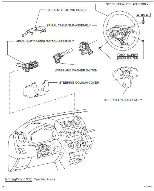
Removal
- Disconnect cable from negative battery terminal
Caution:
Wait at least 90 seconds after disconnecting the cable from the negative (-) battery terminal to prevent airbag and seat belt pretensioner activation.
- Place front wheels facing straight ahead
- Remove steering pad assembly (see page rs- 336)
- Remove steering wheel assembly (see page sr-12)
- Remove steering column cover (see page sr-12)
- Remove spiral cable sub-assembly (see page rs-346)
- Remove wiper and washer switch (see page ww-27)
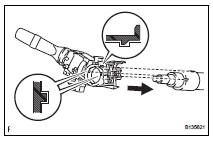
- Remove headlight dimmer switch assembly
- Disconnect the connector.
- Using needle-nose pliers, remove the band clamp as shown in the illustration.
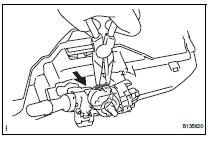
- Using a screwdriver, detach the claws and remove the switch.
Hint:
Tape the screwdriver tip before use.
Inspection
- Inspect headlight dimmer switch assembly
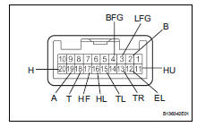
- Measure the resistance of the switch.
Standard resistance:
Light control switch 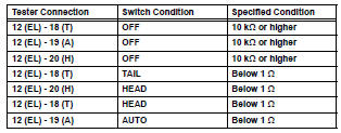
Headlight dimmer switch 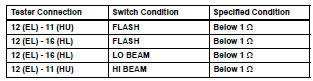
Turn signal switch 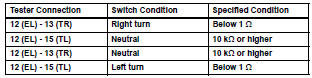
Fog light switch 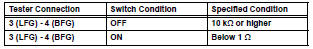
If the result is not as specified, replace the dimmer switch assembly.
Installation
- Install headlight dimmer switch assembly
- Attach the claw to install the headlight dimmer switch with the claw as shown in the illustration.
- Install the headlight dimmer switch with the clamp.
- Connect the connector.
- Install wiper and washer switch assembly (see page ww-29)
- Install spiral cable sub-assembly (see page rs-347)
- Install steering column cover (see page sr- 20)
- Install steering wheel assembly (see page sr-21)
- Place front wheels facing straight ahead
- Inspect steering wheel center point
- Install steering pad assembly (see page rs- 336)
- Connect cable to negative battery terminal
- Inspect steering pad assembly (see page rs- 337)
- Check srs warning light
- Check the srs warning light (see page rs-337).
 Footwell light
On-vehicle inspection
Inspect footwell light
Connect the battery's positive (+) lead to terminal 2
and the negative (-) lead to terminal 1, then check
that the light comes on.
Ok: ...
 Hazard warning switch
Components
Removal
Disconnect cable from negative battery
terminal
Caution:
Wait at least 90 seconds after disconnecting the
cable from the negative (-) battery terminal to
prevent ai ...
Other materials:
Trailer towing tips
Your vehicle will handle differently
when towing a trailer. Help
to avoid an accident, death or
serious injury, keep the following
in mind when towing:
Speed limits for towing a
trailer vary by state or province.
Do not exceed the
posted towing speed limit.
Toyota recommends that the
vehicle- ...
Vehicle lift and support locations
Notice about vehicle condition when
jacking up vehicle
The vehicle must be unloaded before jacking up /
lifting up the vehicle. Never jack up / lift up a heavily
loaded vehicle.
When removing heavy parts such as the engine and
transmission, the center of gravity of the vehicle
m ...
Gauges and meters (with 12.3-inch multi-information display)
The meters display various drive information.
Meter display
â– Locations of gauges and meters
The meter type can be changed on
of the multi-information display.
Type 1/Type 2
The units of measure may differ depending on the intended destination of
the vehicle.
Multi-information display
Presen ...
