Toyota RAV4 (XA40) 2013-2018 Service Manual: Hazard warning switch
Components
Removal
- Disconnect cable from negative battery terminal
Caution:
Wait at least 90 seconds after disconnecting the cable from the negative (-) battery terminal to prevent airbag and seat belt pretensioner activation.
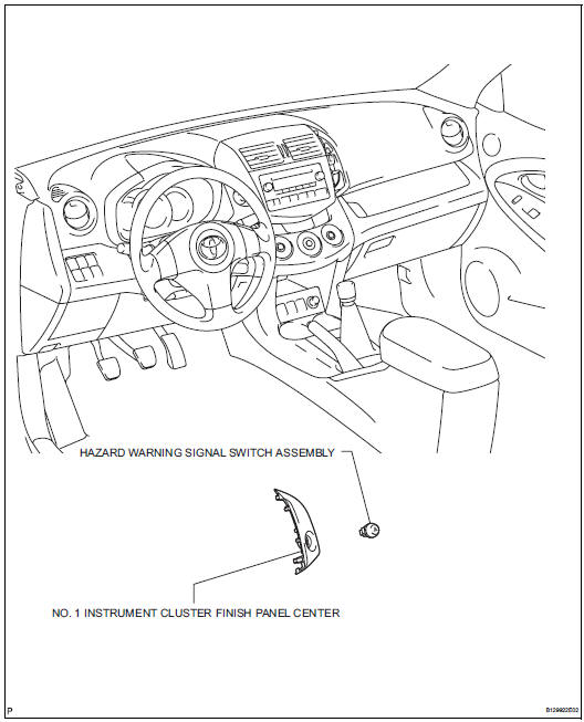
- Remove no. 1 Instrument cluster finish panel center (see page ip-5)
- Remove hazard warning signal switch assembly
- Detach the 2 claws and remove the switch.
Inspection
- Inspect hazard warning signal switch assembly
- Measure the resistance of the switch.
Standard resistance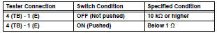
If the result is not as specified, replace the switch assembly.
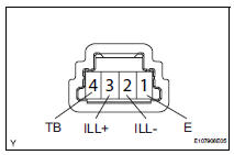
- Inspect the switch illumination.
- Connect the battery positive (+) lead to terminal 3 (ill+) and the negative (-) lead to terminal 2 (ill-), then check that the light comes on.
Ok: led comes on.
If the result is not as specified, replace the light.
Installation
- Install hazard warning signal switch assembly
- Attach the 2 claws to install the switch.
- Install no. 1 Instrument cluster finish panel center (see page ip-10)
- Connect cable to negative battery terminal
 Headlight dimmer switch
Precaution
Precaution for vehicle with srs
Some procedures in this section may affect the
supplemental restraint system (srs). Prior to
performing the procedures, read the srs section's
...
 Front door courtesy switch
Components
Removal
Hint:
Use the same procedures for the rh and lh sides.
The procedures listed below are for the lh side.
Disconnect cable from negative battery
terminal
Cautio ...
Other materials:
Tire information
Typical tire symbols
Full-size tire
Compact spare tire
Tire size
DOT and Tire Identification Number (TIN)
Location of treadwear indicators
Tire ply composition and materials
Plies are layers of rubber-coated parallel cords. Cords are the strands
which form the plies in a tire.
Radial tir ...
Instrument cluster
For the purpose of explanation, the following illustrations display all
warning lights and indicators illuminated.
â– With 7-inch multi-information display
The display of the speedometer can be selected from two types,
analog or digital.
When analog speedometer is displayed
The units used on the m ...
Air outlets and air flow
Upper body
Upper body and feet
Feet
Feet and windshield
Switching between outside air and recirculated air modes
Press .
The mode switches between outside air mode (indicator off) and recirculated
air mode (indicator on) each time
is pressed.
Adjusting the pos ...
