Toyota RAV4 (XA40) 2013-2018 Service Manual: High mounted stop light assembly
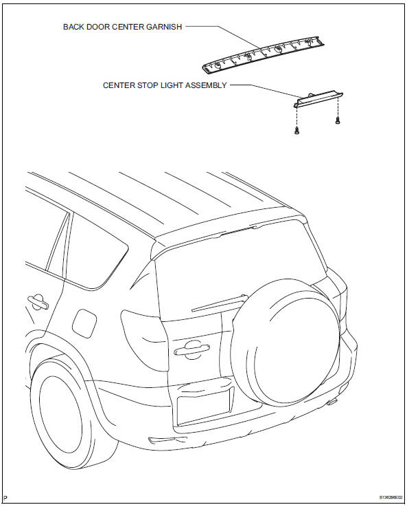
Components
Removal
- Disconnect cable from negative battery terminal
Caution:
Wait at least 90 seconds after disconnecting the cable from the negative (-) battery terminal to prevent airbag and seat belt pretensioner activation.
- Remove back door center garnish (see page ed-59)
- Remove center stop light assembly
- Disconnect the connector.
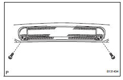
- Remove the 2 screws and center stop light.
Installation
- Install center stop light assembly
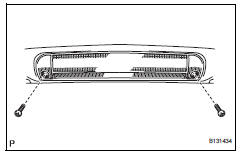
- Install the center stop light with the 2 screws.
- Connect the connector.
- Install back door center garnish (see page ed-67)
- Connect cable to negative battery terminal
 License plate light assembly
Components
Removal
Disconnect cable from negative battery
terminal
Caution:
Wait at least 90 seconds after disconnecting the
cable from the negative (-) battery terminal to
prevent ai ...
 Map light assembly
Components
Removal
Disconnect cable from negative battery
terminal
Caution:
Wait at least 90 seconds after disconnecting the
cable from the negative (-) battery terminal to
prevent ai ...
Other materials:
Head restraints
Head restraints are provided
for all seats.
WARNING
â– Head restraint precautions
Observe the following precautions
regarding the head restraints.
Failure to do so may result in
death or serious injury.
Use the head restraints
designed for each respective
seat.
Adjust the head restraints to th ...
Fuel pump control circuit
Description
When the engine is cranked, the starter relay drive signal output from the
star terminal of the ecm is
input into the sta terminal of the ecm, and ne signal generated by the
crankshaft position sensor is also
input into the ne+ terminal. Thus, the ecm interprets that the engine is ...
Removal
Hint:
Use the same procedures for the rh side and lh side.
The procedures listed below are for the lh side.
Remove roof drip side finish moulding lh
Remove the 2 roof drip moulding joint covers from
the vehicle body.
Remove the roof drip side finish moulding and no. 2
Center ...
