Toyota RAV4 (XA40) 2013-2018 Service Manual: Diagnosis system
- Description
When troubleshooting obd ii (on-board diagnostics) vehicles, the intelligent tester (complying with sae j1987) must be connected to the dlc3 (data link connector 3) of the vehicle. Various data in the vehicle's ecm (engine control module) can be then read.
Obd ii regulations require that the vehicle's on-board computer illuminate the mil (malfunction indicator lamp) on the instrument panel when the computer detects a malfunction in:
The emission control system components.- The powertrain control components (which affect vehicle emissions).
- The computer itself.
In addition, if the applicable dtcs (diagnostic trouble codes) prescribed by sae j2012 are not recorded on 3 consecutive trips, the mil turns off automatically but the dtcs remain recorded in the ecm memory.
 To
To
check dtcs, connect the intelligent tester to the
dlc3. The tester displays dtcs, freeze frame data, and
a variety of the engine data. The dtcs and freeze frame
data can be erased with the tester (see page es-35).
In order to enhance obd function on vehicles and develop the off-board diagnosis system, can (controller area network) communication is introduced in this system. It minimizes the gap between technician skills and vehicle technology. Can is a network, which uses a pair of data transmission lines, spanning multiple computers and sensors. It allows high speed communication between the systems and simplifies the wire harness connection.
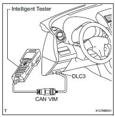
Since this system is equipped with the can communication, connecting the can vim (vehicle interface module) to the intelligent tester is necessary to display any information from the ecm. (Also the communication between the intelligent tester and the ecm uses can communication signals.) When confirming the dtcs and any data of the ecm, connect the can vim between the dlc3 and the intelligent tester.
- Normal mode and check mode
The diagnosis system operates in normal mode during normal vehicle use. In normal mode, 2 trip detection logic is used to ensure accurate detection of malfunctions. Check mode is also available as an option for technicians. In check mode, 1 trip detection logic is used for simulating malfunction symptoms and increasing the system's ability to detect malfunctions, including intermittent problems (intelligent tester only) (see page es-38).
- 2 Trip detection logic
When a malfunction is first detected, the malfunction is temporarily stored in the ecm memory (1st trip). If the same malfunction is detected during the next subsequent drive cycle, the mil is illuminated (2nd trip).
- Freeze frame data
Freeze frame data records the engine conditions (fuel system, calculated engine load, engine coolant temperature, fuel trim, engine speed, vehicle speed, etc.) When malfunctions are detected. When troubleshooting, freeze frame data can help determine if the vehicle was moving or stationary, if the engine was warmed up or not, if the air-fuel ratio was lean or rich, and other data from the time the malfunction occurred.
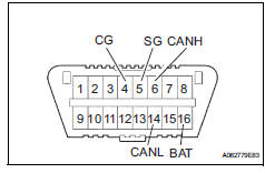
- Dlc3 (data link connector 3)
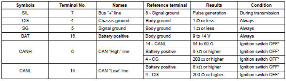
Caution:
*: Before measuring the resistance, leave the vehicle as is for at least 1 minute and do not operate the ignition switch, any other switches or the doors.
If the result is not as specified, the dlc3 may have a malfunction. Repair or replace the harness and connector.
Hint:
The dlc3 is the interface prepared for reading various data from the vehicle's ecm. After connecting the cable of the intelligent tester to the can vim, turn the ignition switch on and turn the tester on. If a communication failure message is displayed on the tester screen (on the tester: unable to connect to vehicle), a problem exists in either the vehicle or tester. In order to identify the location of the problem, connect the tester to another vehicle.
If communication is normal: inspect the dlc3 on the original vehicle.
If communication is still not possible: the problem is probably in the tester itself. Consult the service department listed in the instruction manual.
- Battery voltage
Standard battery voltage: 11 to 14 v
If the voltage is below 11 v, replace or recharge the battery before proceeding.
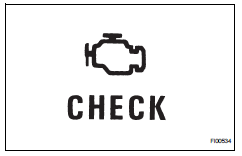
- Mil (malfunction indicator lamp)
- The mil is illuminated when the ignition switch is first turned on (the engine is not running).
- The mil should turn off when the engine is started. If the mil remains illuminated, the diagnosis system has detected a malfunction or abnormality in the system.
Hint:
If the mil is not illuminated when the ignition switch is first turned on, check the mil circuit (see page es-386).
- All readiness
For the vehicle, using the intelligent tester allows readiness codes corresponding to all dtcs to be read.
When diagnosis (normal or malfunctioning) has been complete, readiness codes are set. Select the following menu items on the intelligent tester: enhanced obd ii / monitor status.
 Terminals of ecm
Hint:
The standard normal voltage between each pair of ecm
terminals is shown in the table below. The appropriate
conditions for checking each pair of terminals are also
indicated. The result ...
 Dtc check / clear
Notice:
When the diagnosis system is changed from normal
mode to check mode or vice versa, all dtcs and freeze
frame data recorded in normal mode are erased. Before
changing modes, always check an ...
Other materials:
Tires
Replace or rotate tires in accordance with maintenance schedules
and treadwear.
Checking tires
New tread
Treadwear indicator
Worn tread
The location of treadwear indicators
is shown by the ¢Â§twi¢¸ or ¢Â§ƒ´¢¸
marks, etc., Molded on the si ...
Precaution
Caution:
Replace the faulty parts of the seat belt systems (outer
belt, inner belt, bolts, nuts, adjustable shoulder anchor,
tether anchor hardware and other related parts). When
inspecting a vehicle that was in a collision, be sure to
check all of the seat belt systems regardless of whethe ...
Ecm communication stop mode (2005/11-2006/01)
Description
Wiring diagram
Inspection procedure
Notice:
Turn the ignition switch off before measuring the resistances of the
main wire and the branch
wire.
After the ignition switch is turned off, check that the key reminder
warning system and light
reminder warning system ...
