
Toyota RAV4 (XA40) 2013-2018 Service Manual: Slip indicator light remains on
Description
The slip indicator blinks during vsc and/or trc operation.
When the system fails, the slip indicator comes on to warn the driver.
For 2wd: with auto lsd switch on, when the hydraulic brake booster is at a high temperature, the slip indicator illuminates.
Wiring diagram
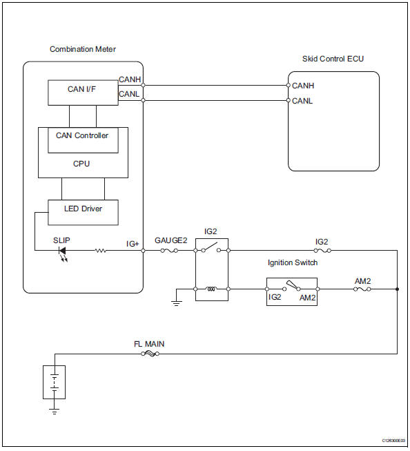
Inspection procedure
Notice:
When replacing the abs and traction actuator, perform the zero point calibration (see page bc- 24).
- Check can communication system
- Check if the can communication system dtc is output (see page ca-34).
Result 


- Check skid control ecu connector
- Check if the skid control ecu connector is securely connected.
Ok: the connector is securely connected.


- Check combination meter
- Check the combination meter (see page me-15).


Replace abs and traction actuator assembly
 Brake warning light does not come on
Wiring diagram
Refer to the brake warning light circuit (see page bc-145).
Inspection procedure
Check can communication system
Check if the can communication system dtc is output
(see pa ...
 Slip indicator light does not come on
Description
Refer to the description of "slip indicator light remains on" (see page
bc-152).
Wiring diagram
Refer to the slip indicator light circuit (see page bc-152).
Inspection proc ...
Other materials:
Diagnostic trouble code chart
Hint:
If no abnormality is found when inspecting parts, check the
skid control ecu and check for poor contact at the ground
points.
If a dtc is displayed during the dtc check, check the
circuit for the dtc listed in the table below. For details of
each dtc, refer to the page indicated. ...
Room light assembly
Components
Removal
Disconnect cable from negative battery
terminal
Caution:
Wait at least 90 seconds after disconnecting the
cable from the negative (-) battery terminal to
prevent airbag and seat belt pretensioner activation.
Remove room light lens
Using a screwdriver ...
Emission inspection
and maintenance (i/m)
programs
Some states have vehicle emission inspection programs which
include obd (on board diagnostics) checks. The obd system
monitors the operation of the emission control system.
If the malfunction indicator lamp comes on
The obd system determines that a problem exists somewhere in the
emission contr ...
