Toyota RAV4 (XA40) 2013-2018 Service Manual: Installation
Caution:
Be sure to read the precautionary notices concerning the srs airbag system before servicing it (see page rs-1).
- Install steering pad assembly
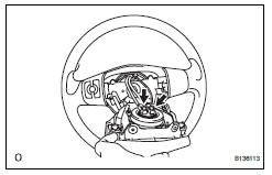
- Support the steering pad with one hand as shown in the illustration.
- Connect the 2 airbag connectors.
Notice:
When handling the airbag connector, do not damage the airbag wire harness.
- Connect the horn connector.
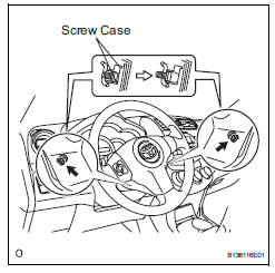
- Install the steering pad after confirming that the circumference grooves of the screws are caught on the screw case.
- Using a t30 "torx" driver, install the 2 screws.
Torque: 8.8 N*m (90 kgf*cm, 78 in.*Lbf)
- Connect cable to negative battery terminal
- Inspect steering pad assembly
- Check for cuts, cracks or discoloration on the steering pad outer surface and in the grooved portion.
- Check that the horn sounds.
- Check srs warning light
- Check the srs warning light (see page rs-34).
 Removal
Caution:
Be sure to read the precautionary notices concerning the
srs airbag system before servicing it (see page rs-1).
Disconnect cable from negative battery
terminal
Caution:
Wait at le ...
 Disposal
Hint:
When scrapping a vehicle equipped with an srs or disposing
of the steering pad, be sure to deploy the airbag first in
accordance with the procedure described below. If any
abnormality occurs ...
Other materials:
System voltage
Description
The battery supplies electricity to the ecm even when the ignition switch is
in the off position. This
power allows the ecm to store data such as dtc history, freeze frame data and
fuel trim values. If the
battery voltage falls below a minimum level, the memory is cleared and ...
Short in driver side squib circuit
Description
The driver side squib circuit consists of the center airbag sensor, the
spiral cable and the steering pad.
The circuit instructs the srs to deploy when the deployment conditions are met.
These dtcs are recorded when a malfunction is detected in the driver side squib
circui ...
Functions included in
LTA system
â– Lane departure alert function
When the system determines that the vehicle might depart
from its lane or course*, a warning
is displayed on the multi-information
display, and a warning
buzzer will sound to alert the
driver.
When the warning buzzer sounds,
check the area around your vehicle
and c ...
