Toyota RAV4 (XA40) 2013-2018 Service Manual: Removal
Caution:
Be sure to read the precautionary notices concerning the srs airbag system before servicing it (see page rs-1).
- Disconnect cable from negative battery terminal
Caution:
Wait at least 90 seconds after disconnecting the cable from the negative (-) battery terminal to prevent airbag and seat belt pretensioner activation.
- Remove steering pad assembly
- Straighten the front wheels.
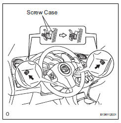
- Using a t30 "torx" driver, loosen the 2 screws until the groove along each screw circumference catches on the screw case.
- Pull out the steering pad from the steering wheel and support the steering pad with one hand as shown in the illustration.
Notice:
When removing the steering pad, do not pull the airbag wire harness.
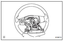
- Using a screwdriver, disconnect the 2 airbag connectors.
Caution:
When handling the airbag connector, do not damage the airbag wire harness.
- Disconnect the horn connector and remove the steering pad.
 On-vehicle inspection
Check steering pad assembly (vehicle not involved in collision and
airbag not deployed)
Perform a diagnostic system check (see page rs-
49).
With the steering pad (with airbag) ins ...
 Installation
Caution:
Be sure to read the precautionary notices concerning the
srs airbag system before servicing it (see page rs-1).
Install steering pad assembly
Support the steering pad with one ...
Other materials:
Illumination circuit
Description
The main body ecu receives information regarding the door courtesy switch and
door lock position
switch, and turns on the room light.
Wiring diagram
Inspection procedure
Perform active test by intelligent tester (main body ecu)
Connect the intelligent tester (with can ...
Disassembly (2005/11-2006/01)
Remove front axle inboard joint boot no. 2 Clamp lh
One touch type:
Using a screwdriver, remove the inboard joint
boot clamp, as shown in the illustration.
Claw engagement type:
Using needle-nose pliers, remove the inboard
joint boot clamp, as shown in the illustra ...
Test mode procedure
Test mode check
Hint:
When entering the test mode, the tire pressure
warning ecu sets all the test dtcs first. After
completing the test mode for each inspection item, the
dtcs that are determined normal by the tire pressure
warning ecu will be erased.
The dtcs for other inspec ...
