Toyota RAV4 (XA40) 2013-2018 Service Manual: Installation
- Install knock sensor
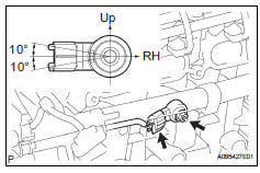
- Install the sensor with the nut.
Torque: 20 n*m (205 kgf*cm, 15 ft.*Lbf)
Notice:
Make sure that the knock sensor is in the correct position.
- Connect the sensor connector.
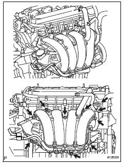
- Install intake manifold insulator
- install the intake manifold insulator onto the cylinder block.
- Install intake manifold
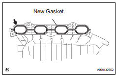
- Install a new gasket into the intake manifold.
- Install the intake manifold with the 5 bolts and 2 nuts.
Torque: 30 n*m (305 kgf*cm, 22 ft.*Lbf)
- Fit the union to check valve hose into the vacuum hose clamp.
- Install the wire harness clamp.
- Connect the camshaft timing oil control valve connector.
- Connect the union to check valve hose to the brake booster.
- Connect heater water outlet hose
- Install the heater water outlet hose to the water bypass pipe and heater radiator unit.
- Connect heater water inlet hose
- Install the heater water inlet hose to the cylinder head and heater radiator unit.
- Install the hose clamp.
- Install fuel tube
- Install fuel delivery pipe (see page fu-13)
- Install throttle body (see page es-413)
- Install air cleaner cap (see page es-413)
- Connect cable to negative battery terminal
- Add engine coolant (see page co-6)
- Check for engine coolant leakage (see page co-1)
- Check for fuel leakage (see page fu-14)
- Install no. 1 Engine cover (see page es-414)
 Inspection
Inspect knock sensor
Measure the resistance of the sensor.
Standard resistance
If the result is not as specified, replace the knock
sensor. ...
 Integration relay
On-vehicle inspection
Disconnect cable from negative battery
terminal
Caution:
Wait at least 90 seconds after disconnecting the
cable from the negative (-) battery terminal to
prevent airb ...
Other materials:
Listening to a usb
memory device
Connecting a usb memory device enables you to enjoy music
from the vehicle speakers.
Touch “usb” on the audio source selection screen.
Connecting a usb memory device
Audio control screen
Pressing the “audio” button displays the audio control screen from
any screens of the selected so ...
Problem symptoms table
Hint:
Use the table below to help determine the cause of the
problem symptom. The potential causes of the symptoms
are listed in order of probability in the "suspected area"
column of the table. Check each symptom by checking the
suspected areas in the order they are listed. Re ...
Steering wheel audio switches
Some audio features can be controlled using the switches on
the steering wheel.
Operation may differ depending on the type of audio system or
navigation system. For details, refer to the manual provided with
the audio system or navigation system.
Operating the audio system using the steering ...
