Toyota RAV4 (XA40) 2013-2018 Service Manual: On-vehicle inspection
Notice:
- Perform the maf meter inspection according to the procedures below.
- Only replace the maf meter when both the long ft#1 value and maf value in the data list (with the engine stopped) are not within the normal operating range.
- Inspect mass air flow meter
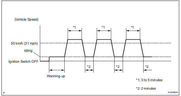
- Perform confirmation driving pattern.
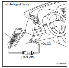
- Connect the intelligent tester to the dlc3.
- Turn the ignition switch on.
- Turn the tester on.
- Clear the dtcs (see page es-35).
- Start the engine and warm it up with all accessory switches off until the engine coolant temperature is 75°c (167°f) or more.
- Drive the vehicle at 50 km/h (31 mph) or more for 3 to 5 minutes*1.
- Allow the engine to idle for 2 minutes*2.
- Perform steps *1 and *2 at least 3 times.
- Read the value using the intelligent tester (long ft#1).
- Select the following menu items: diagnosis / enhanced obd ii / data list / primary / long ft#1.
- Read the values displayed on the tester.
Standard value: within -15 to +15%
If the result is not within the specified range, perform the inspection below.
- Read the value using the intelligent tester (maf).
Notice:
- Turn off the engine.
- Perform the inspection with the vehicle indoors and on a level surface.
- Perform the inspection of the maf meter while it is installed to the air cleaner case (installed to the vehicle).
- During the test, do not use the exhaust air duct to perform suction on the exhaust pipe.
- Turn the ignition switch to acc.
- Turn the ignition switch on (do not run the engine).
- Turn the tester on.
- Select the following menu items: diagnosis / enhanced obd ii / data list / primary / maf.
- Wait 30 seconds, and read the values on the intelligent tester.
Standard condition: less than 0.45 G/sec.
- If the result is not as specified, replace the maf meter.
- If the result is within the specified range, inspect the cause of the extremely rich or lean air-fuel ratio (see page es-147).
 Mass air flow meter
Components
...
 Removal
Disconnect cable from negative battery terminal
Caution:
Wait at least 90 seconds after disconnecting the
cable from the negative (-) battery terminal to
prevent airbag and seat belt pretensi ...
Other materials:
Parking Support Brake function
(static objects)
If the sensors detect a static object, such as a wall, in the
traveling direction of the vehicle and the system determines
that a collision may occur due to the vehicle suddenly moving
forward due to an accidental accelerator pedal operation, the
vehicle moving the unintended direction due to the wr ...
Disposal
Hint:
When scrapping a vehicle equipped with an srs or disposing
of the curtain shield airbag assembly, be sure to deploy the
airbag first in accordance with the procedure described
below. If any abnormality occurs with the airbag deployment,
contact the service dept. Of toyota motor sales,
u. ...
Tire pressure warning valve and transmitter
Components
Removal
Remove front tire
Remove rear tire
Remove tire pressure warning valve subassembly
Remove the valve core and cap, and release air
from the tire.
After ensuring that air is sufficiently released,
remove the nut and washer that are used to fix the
tire pres ...
