Toyota RAV4 (XA40) 2013-2018 Service Manual: Only driver door lock / unlock functions do not operate
Description
The main body ecu receives lock / unlock switch signals and activates the door lock motor accordingly.
Wiring diagram
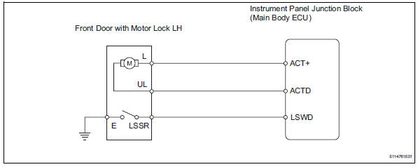
Inspection procedure
- Perform active test by intelligent tester (door lock)
- Select the active test, use the intelligent tester to generate a control command, and then check that the doors lock / unlock.
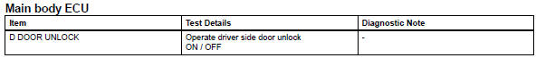
Ok: doors can lock / unlock

- Read value of intelligent tester (lock position switch)
- Use the data list to check if the door lock is functioning properly.
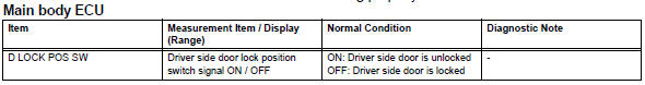
Ok: when the door lock is operating, the intelligent tester should display as shown in the table.

- Inspect front door with motor lock assembly lh
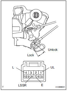
- Apply the battery voltage to the motor terminals and check the operation of the door lock motor.
Ok 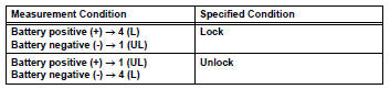
- Measure the resistance of the door lock position switch.
Standard resistance 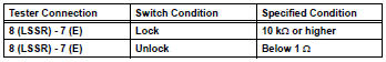

- Check wire harness (door lock - ecu)
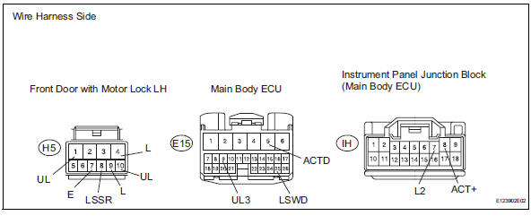
- Disconnect the h5 door lock connector.
- Disconnect the e15 ecu connector.
- Disconnect the ih junction block connector.
- Measure the resistance of the wire harness side connectors.
Standard resistance 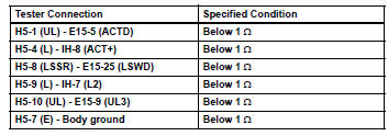

Replace instrument panel junction block (main body ecu)
 All doors cannot be locked / unlocked simultaneously
Description
The main body ecu receives switch signals from the door control switch on the
power window regulator
master switch, door control switch and driver side door key cylinder, and
activat ...
 Only passenger door lock / unlock functions do not operate
Description
The main body ecu receives lock / unlock switch signals and activates the
door lock motor accordingly.
Wiring diagram
Inspection procedure
Read value of intelligent tester (lo ...
Other materials:
Ig2 relay
On-vehicle inspection
Disconnect cable from negative battery
terminal
Caution:
Wait at least 90 seconds after disconnecting the
cable from the negative (-) battery terminal to
prevent airbag and seat belt pretensioner activation.
Remove ig2 relay
Remove the no. 1 Engine room re ...
Before refueling the vehicle
Close all the doors and windows, and turn the engine switch to the
“lock” position (vehicles without a smart key system) or off (vehicles
with a smart key system).
Confirm the type of fuel.
Fuel types
Unleaded gasoline (octane rating 87 [research octane number 91] or
higher)
Cauti ...
Downhill assist control indicator light remains on
Description
When the downhill assist control switch is pushed on, the downhill assist
control function is available and
the downhill assist control indicator light illuminates.
Hint:
Even if the downhill assist control switch is pressed, the downhill assist
control indicator light will blink ...
