Toyota RAV4 (XA40) 2013-2018 Service Manual: Open in stop light switch circuit
Description
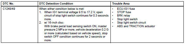
The skid control ecu detects the brake operating conditions through a signal transmitted by the stop light switch. The skid control ecu incorporates an open circuit detection circuit. This dtc is set under either of the following conditions:
- An open is detected in the stop light signal input line when the stop light switch is off.
- An open is detected in the stop light circuit lead to the ground when the stop light switch is off.
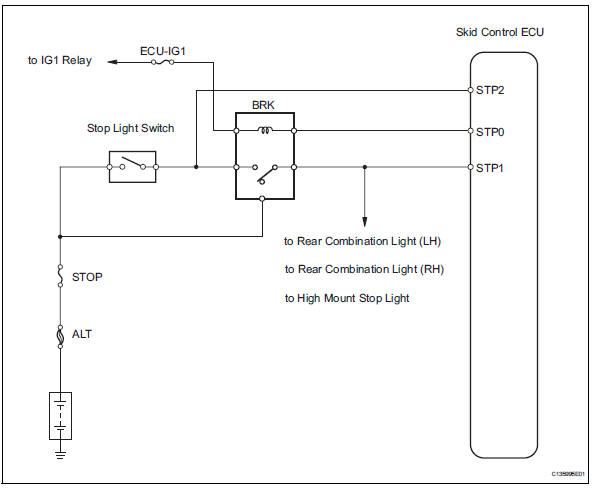
Wiring diagram
Inspection procedure
- Read value of intelligent tester (stop light switch)
- Check the data list for proper functioning of the stop light switch.
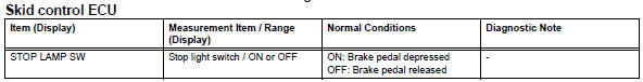
Ok: on (brake pedal is depressed) appears on the screen.


- Check wire harness (stp voltage)
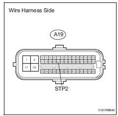
- Disconnect the a19 ecu connector.
- Measure the voltage of the wire harness side connector.
Standard voltage 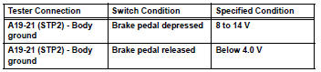


Replace abs and traction actuator assembly
- Inspect fuse (stop, ecu-ig1)
- Remove the stop fuse and ecu-ig1 fuse from the instrument panel junction block.
- Measure the resistance of the fuse.
Standard resistance:
below 1 


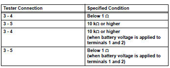
- Inspect stop light control relay (marking: brk)
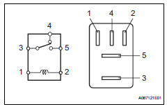
- Remove the stop light control relay from the engine room no. 1 Relay block.
- Measure the resistance of the relay.


- Inspect stop light switch assembly
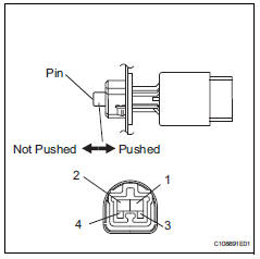
- Disconnect the stop light switch connector.
- Measure the resistance of the switch.
Standard resistance 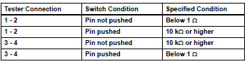


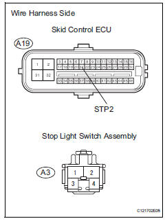
- Check wire harness (skid control ecu - stop light switch)
- Disconnect the a19 ecu connector.
- Disconnect the a3 switch connector.
- Measure the resistance of the wire harness side connectors.
- Disconnect the a19 ecu connector.
- Disconnect the a3 switch connector.
- Measure the resistance of the wire harness side connectors.
Standard resistance 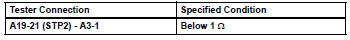

- Reconfirm dtc
- Clear the dtc (see page bc-47).
- Check if the same dtc is output (see page bc-47).
Result 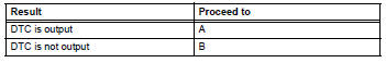


Replace abs and traction actuator assembly
 Master cylinder pressure sensor malfunction
Description
The master cylinder pressure sensor is connected to the skid control ecu in
the abs and traction
actuator.
Dtc c1281/81 can be detected when the master cylinder pressure sensor ...
 Open in pump motor circuit
Description
The motor relay drives the pump motor based on a signal from the skid control
ecu.
Wiring diagram
Refer to dtc c0273/13, c0274/14, c1361/91 (see page bc-79).
Inspection proce ...
Other materials:
Communication
Description
The skid control ecu sends signals such as cruise control cancel demand
signals and brake operation
demand from ecm response signals to the ecm when the cruise control system is in
operation.
Inspection procedure
Hint:
This circuit uses can communication. Therefore, if t ...
Armrest
Front (vehicles with slide function)
Slide the console box lid forward
or backward as needed.
Pull the lid forward by holding
the front of the lid.
Rear
Fold down the armrest for use.
Notice
To prevent damage to the armrest
Do not apply too much load on the armrest. ...
How to proceed with troubleshooting
Hint:
Use these procedures to troubleshoot the engine immobiliser
system.
*: Use the intelligent tester.
Vehicle brought to workshop
Inspect battery voltage
Standard voltage:
11 to 14 v
If the voltage is below 11 v, recharge or replace the battery
before proceeding.
cran ...
