Toyota RAV4 (XA40) 2013-2018 Service Manual: Precaution
Caution:
- The vehicle is equipped with a supplemental restraint system (srs), which consists of a steering pad, front passenger airbag, curtain shield airbag, front seat side airbag, seat belt pretensioner, center airbag sensor, front airbag sensor, side airbag sensor, rear airbag sensor, occupant classification ecu and seat position airbag sensor. Failure to carry out service procedures in the correct sequence could cause srs parts to unexpectedly deploy and possibly lead to serious injuries. Furthermore, if a mistake is made when servicing srs parts, they may fail to operate when required. Before performing servicing (including installation/removal, inspection and replacement of parts), be sure to read the following precautions.
- Before starting work, wait at least 90 seconds after the ignition switch is turned off and after the cable of the negative (-) battery terminal is disconnected. (Srs parts are equipped with a backup power source. If work is started within 90 seconds of turning the ignition switch off and disconnecting the cable from the negative (-) battery terminal, srs parts may deploy.) (The srs is equipped with a back-up power source, so if work is started within 90 seconds of disconnecting the negative (-) terminal cable of the battery, the srs may be deployed).
- Do not expose srs parts directly to hot air or flames.
Notice:
- Malfunction symptoms of srs parts are difficult to confirm. Dtcs are the most important source of information when troubleshooting. During troubleshooting, always confirm dtcs before disconnecting the cable from the negative (-) battery terminal.
- For minor collisions where srs parts do not deploy, always inspect the srs parts.
- Before repair work, remove airbag sensors as necessary if any kind of impact is likely to occur to an airbag sensor during the operation.
- Never use srs parts from another vehicle. When replacing srs parts, replace them with new ones.
- Never disassemble or attempt to repair srs parts.
- If an srs part has been dropped, or if there are any cracks, dents or other defects in the case, bracket or connector, replace the srs part with a new one.
- Use an ohmmeter/voltmeter with high impedance (10 kù/v minimum) for troubleshooting the electrical circuits.
- Information labels are attached to the periphery of srs parts. Follow the cautions and instructions on the labels.
- After work on srs parts is completed, perform the srs warning light check (see page rs-37).
- When the cable is disconnected from the negative (-)
battery terminal, the memory settings of each system
will be cleared. Because of this, be sure to write down
the settings of each system before starting work.
When work is finished, reset the settings of each system as before. Never use a backup power supply from outside the vehicle to avoid erasing the memory in a system.
- If the vehicle is equipped with a mobile communication system, refer to the precautions in the introduction section (see page in-5).
Hint:
In the airbag system, the center airbag sensor, front airbag sensor lh and rh, side airbag sensor lh and rh, and rear airbag sensor lh and rh are collectively referred to as the airbag sensors.
- Handling precautions for airbag sensors
- Before starting the following operations, wait for at least 90 seconds after disconnecting the negative (- ) terminal cable from the battery:
- Replacement of the airbag sensors
- Adjustment of the front/rear doors of the vehicle equipped with the side airbags and curtain shield airbags (fitting adjustment)
- When connecting or disconnecting the airbag sensor connectors, ensure that each sensor is installed in the vehicle.
- Do not use airbag sensors which have been dropped during the operation or transportation.
- Do not disassemble the airbag sensors.
- Inspection procedure for vehicle involved in accident
- When the airbag has not deployed, confirm the dtcs by checking the srs warning light. If there is any malfunction in the srs airbag system, perform troubleshooting.
- When any of the airbags have deployed, replace the airbag sensors and check the installation condition.
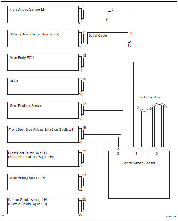
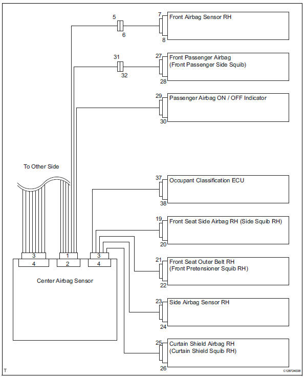
- Srs connector
- Srs connectors are located as shown in the following illustration.
- W/ front seat side airbag and curtain shield airbag
- W/o front seat side airbag and curtain shield airbag
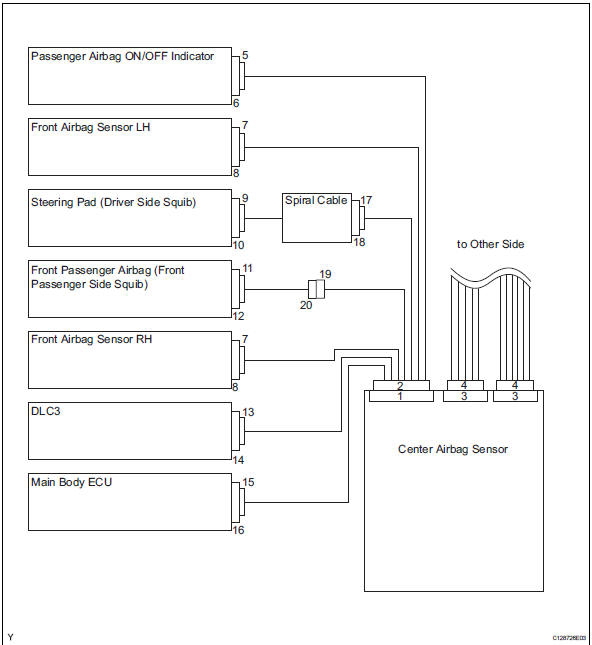
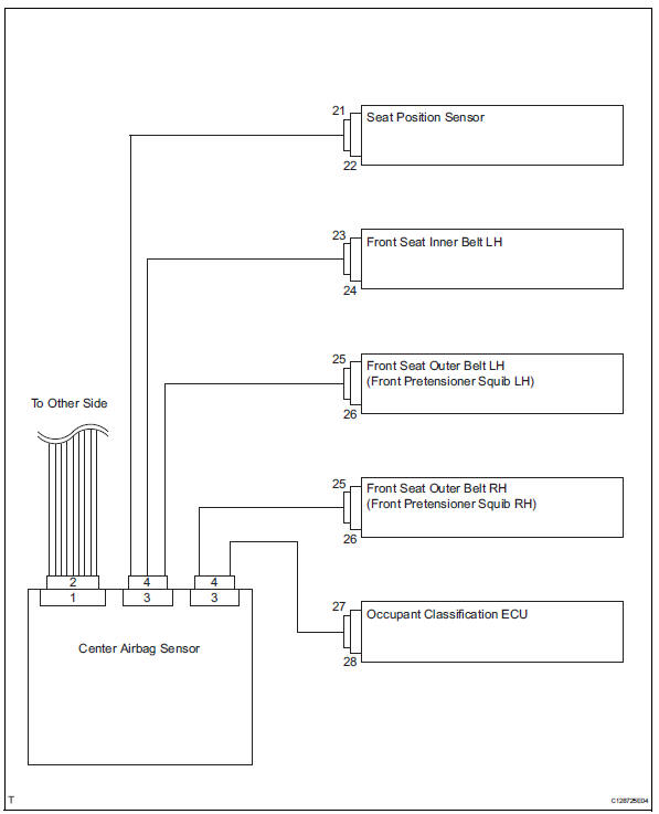
- All connectors in the srs except the seat position sensor connector and the occupant classification ecu connector are colored yellow to distinguish them from other connectors. Some connectors have special functions, and are specially designed for the srs. These connectors use durable gold-plated terminals, and are placed in the locations shown above to ensure high reliability.
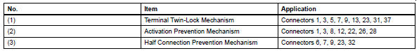
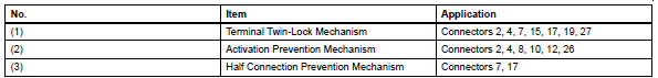
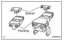
- Terminal twin-lock mechanism: each connector is a two-piece component consisting of a housing and a spacer. This design enables the terminal to be locked securely by two locking devices (the retainer and the lance) to prevent the terminals from becoming disconnected.
- Activation prevention mechanism:
each connector contains a short spring plate.
When the connector is disconnected, the short spring plate creates a short circuit by automatically connecting the positive (+) and negative (-) terminals of the squib.
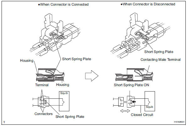
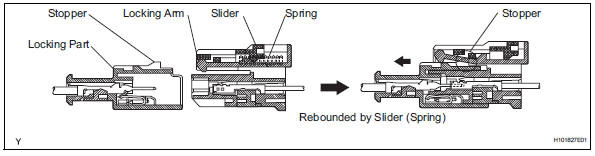
- Half connection prevention mechanism: if the connector is not completely connected, the connector is disconnected by the spring operation so that no continuity exists.
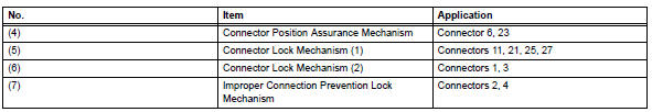
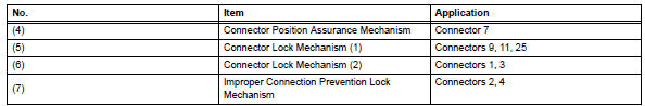
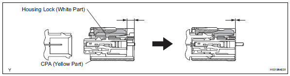
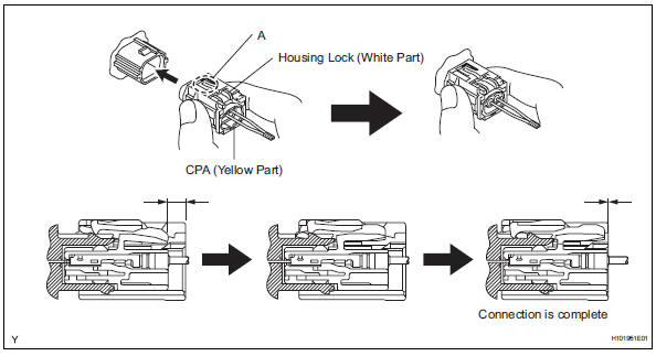
- Connector position assurance mechanism: the cpa (yellow part) slides, which completes the connector engagement, only when the housing lock (white part) is completely engaged.
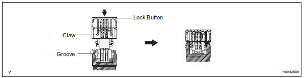
- Connector lock mechanism (1): locking the connector lock button connects the connector.
- Connector lock mechanism (2): both the primary lock with holder lances and the secondary lock with a retainer prevent the connectors from becoming disconnected.
- Improper connection prevention lock mechanism: when connecting the holder, the lever is pushed into the end by rotating around the a axis to lock the holder securely.
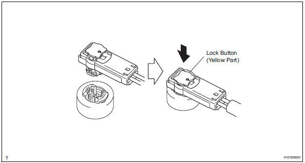
- Disconnection of connectors for steering pad, front passenger airbag assembly (squib side), curtain shield airbag assembly and front seat outer belt assembly
Hint:
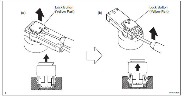
Tape the screwdriver tip before use.
- Release the lock button (yellow part) of the connector using a screwdriver.
- Insert the screwdriver tip between the connector and the base, and then raise the connector.
- Connection of connectors for steering pad, front passenger airbag assembly (squib side), curtain shield airbag assembly and front seat outer belt assembly
- Connect the connector.
- Push the lock button (yellow part) of the connector down securely. (When locking, a click sound can be heard.)
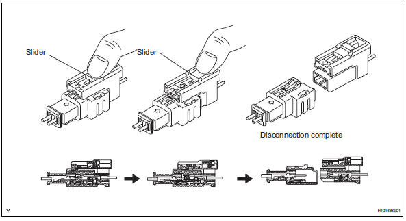
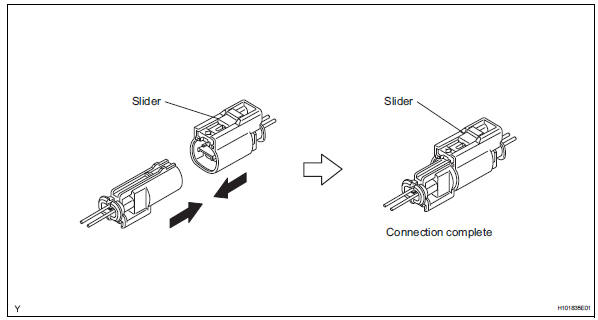
- Disconnection of connectors for front passenger airbag assembly (instrument panel wire side)
- Place a finger on the slider, slide the slider to release the lock, and then disconnect the connector.
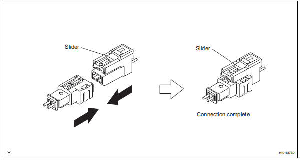
- Connection of connectors for front passenger airbag assembly (instrument panel wire side)
- Connect the connector as shown in the illustration.
(When locking, make sure that the slider returns to its original position and a click sound can be heard.)
Hint:
When connecting, the slider slides. Do not touch the slider while connecting, as this may result in an insecure fit.
- Disconnection of connectors for front seat side airbag assembly
- Place a finger on the slider, slide the slider to release the lock, and then disconnect the connector.
- Connection of connectors for front seat side airbag assembly
- Connect the connector as shown in the illustration.
(When locking, make sure that the slider returns to its original position and a click sound can be heard.)
Hint:
When connecting, the slider slides. Do not touch the slider while connecting, as this may result in an insecure fit.
- Disconnection of connectors for center airbag sensor assembly
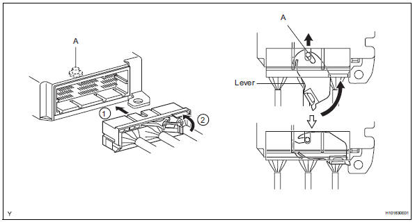
- Pull the lever by pushing part a as shown in the illustration and disconnect the holder (with connectors).
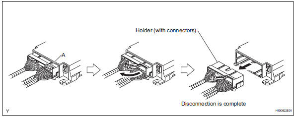
Hint:
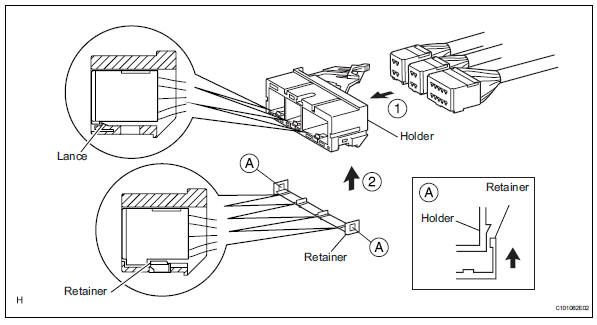
Perform the following procedures when replacing the holder.
- Remove the holder.
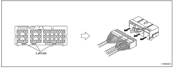
- Using a screwdriver, unlock the retainer.
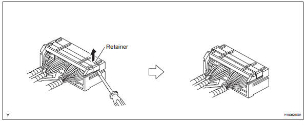
- Release the fitting lances and remove the holder.
- Install the holder.
- Install the connectors into the holder. (When locking, a click sound can be heard.)
Hint:
The retainer is locked when the holder is connected.
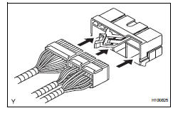
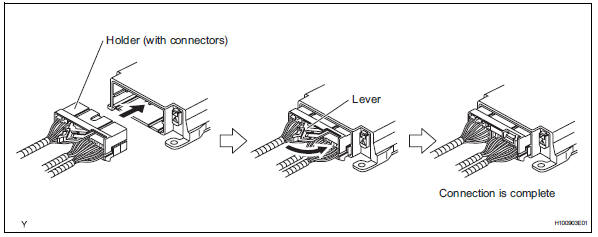
- Connection of connectors for center airbag sensor assembly
- Firmly insert the holder (with connectors) into the center airbag sensor until it cannot be pushed any further.
- Push the lever to connect the holder (with connectors). (When locking, a click sound can be heard.)
Hint:
The holder slides into the center airbag sensor when it is being connected. Do not hold the holder while connecting, as it may result in an insecure fit.
- Disconnection of connectors for front airbag sensor
- Push down the housing lock (white part) and slide the cpa (yellow part). (At this time, the connector cannot be disconnected.)
- Push down the housing lock (white part) again and disconnect the connector.
Hint:
Do not push down part a shown in the illustration when disconnecting.
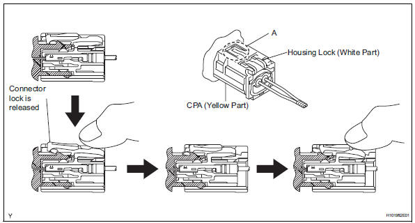
- After disconnecting the connector, check that the position of the housing lock (white part) is as shown in the illustration.
- Connection of connectors for front airbag sensor
- Before connecting the connectors, check that the position of the housing lock (white part) is as shown in the illustration.
- Be sure to engage the connectors until they are locked. (When locking, make sure that a click sound can be heard.)
Hint:
When connecting them, the housing lock (white part) slides. Do not hold the housing lock (white part) and part a, as it may result in an insecure fit.
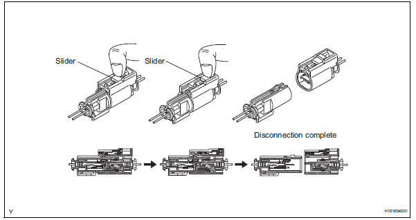
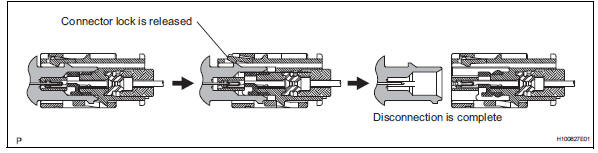
- Disconnection of connectors for side airbag sensor and rear airbag sensor
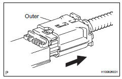
- While holding both sides of the outer connector locking sleeve, slide the outer in the direction shown by the arrow.
- When the connector lock is released, the connectors are disconnected.
Hint:
Be sure to hold both outer flanks. Holding the top and bottom sides will make disconnection difficult.
- Connection of connectors for side airbag sensor and rear airbag sensor
- Connect the connector as shown in the illustration (when locking, make sure that the outer returns to its original position and a click sound can be heard).
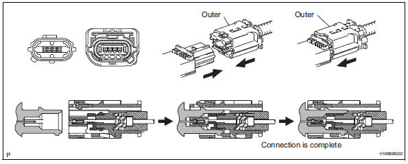
Hint:
When connecting, the outer slides. Do not hold the outer while connecting, as it may result in an insecure fit.
 Airbag system
...
 Parts location
System diagram
...
Other materials:
Steering wheel audio switches
Some audio features can be controlled using the switches on
the steering wheel.
Operation may differ depending on the type of audio system or
navigation system. For details, refer to the manual provided with
the audio system or navigation system.
Operating the audio system using the steering ...
Rear occupant classification sensor rh collision detection
Description
Dtc b1788 is output when the occupant classification ecu receives a collision
detection signal sent by
the rear occupant classification sensor rh when an accident occurs.
Dtc b1788 is also output when the front seat rh is subjected to a strong impact,
even if an actual
acci ...
Summary of the blind spot monitor
The blind spot monitor is a system that has 2 functions;
The blind spot monitor function
Assists the driver in making the decision when changing lanes
The rear cross traffic alert function
Assists the driver when backing up
These functions use same sensors.
Bsm main switch
...
