Toyota RAV4 (XA40) 2013-2018 Service Manual: Skid control buzzer circuit
Description
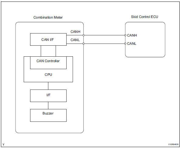
The skid control buzzer sounds while the vsc is activated.
Wiring diagram
Inspection procedure
Notice:
When replacing the abs and traction actuator, perform the zero point calibration (see page bc- 24).
- Check can communication system
- Check if the can communication dtc is output (see page ca-34).
Result 

- Perform active test by intelligent tester (skid control buzzer)
- Select the active test, generate a control command, and then check that the skid control buzzer operate.

Ok: the skid control buzzer can be heard.

- Inspect combination meter
- Inspect the combination meter (see page me-15).


Replace abs and traction actuator assembly
 Auto lsd indicator light does not come on
Description
Refer to the description of "auto lsd indicator light remains on" (see page
bc-164).
Wiring diagram
Refer to the auto lsd indicator light circuit (see page bc-165).
Inspect ...
 Tc and cg terminal circuit
Description
Connecting terminals tc and cg of the dlc3 causes the skid control ecu to
display 2-digit dtcs by
flashing the abs warning light.
Wiring diagram
Inspection procedure
Check dl ...
Other materials:
Setup menu
You can adjust the audio system to your desired settings.
Display “setup” screen
Press the “setup” button to display the “setup” screen.
Select to adjust the settings for
operation sounds, screen animation,
etc.
Select to display the voice settings
screen.
Select to adjus ...
General maintenance
Listed below are the general maintenance items that should be
performed at the intervals specified in the “owner’s warranty
information booklet” or “owner’s manual supplement/scheduled
maintenance guide”. It is recommended that any problem
you notice should be brought to the attentio ...
Cd player operation
Insert disc or select “cd” on the audio source selection screen
with a disc inserted to begin listening to a cd.
Audio control screen
Pressing the “audio” button displays the audio control screen from
any screens of the selected source.
Audio source selection screen
appears
Displ ...
