Toyota RAV4 (XA40) 2013-2018 Service Manual: Tc and cg terminal circuit
Description
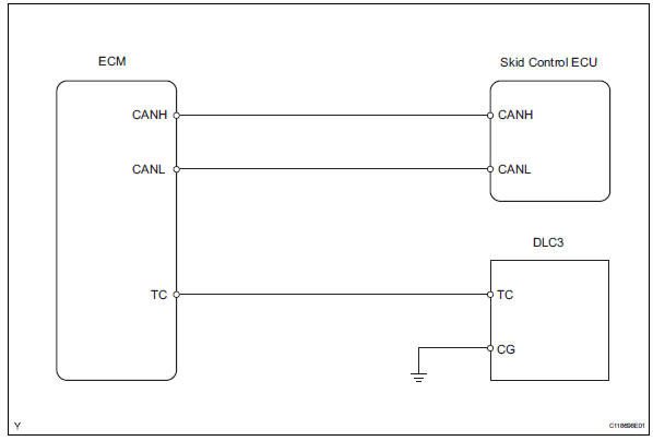
Connecting terminals tc and cg of the dlc3 causes the skid control ecu to display 2-digit dtcs by flashing the abs warning light.
Wiring diagram
Inspection procedure
- Check dlc3 (tc voltage)
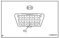
- Turn the ignition switch on.
- Measure the voltage of the dlc3.
Standard voltage 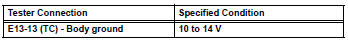


- Check can communication system
- Check the dtc (see page ca-34).
Result 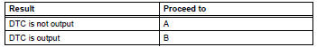

Replace abs and traction actuator assembly
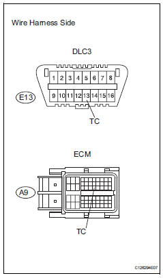
- Check wire harness (dlc3 - ecm and body ground)
- Turn the ignition switch off.
- Disconnect the a12 ecm connector.
- Measure the resistance of the wire harness side connectors.
Standard resistance 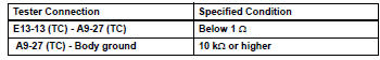

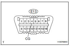
- Check wire harness (dlc3 - body ground)
- Measure the resistance of the dlc3.
Standard resistance 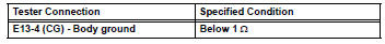

- Check can communication system
- Check if the can communication dtc is output (see page ca-34).
Result 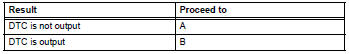

Replace abs and traction actuator assembly
 Skid control buzzer circuit
Description
The skid control buzzer sounds while the vsc is activated.
Wiring diagram
Inspection procedure
Notice:
When replacing the abs and traction actuator, perform the zero point
calib ...
 Ts and cg terminal circuit
Description
If the vehicle is stationary during sensor check mode, speed sensor
malfunctions cannot be detected. The
vehicle must be driven for speed sensor malfunctions to be detected.
Hint:
...
Other materials:
Wireless remote
control/electronic
key battery
Replace the battery with a new one if it is depleted.
You will need the following items:
Flathead screwdriver
Small flathead screwdriver
Lithium battery cr2016 (vehicles without a smart key system), or
cr2032 (vehicles with a smart key system)
Replacing the battery
Vehicles without a ...
Switch failure
Description
This dtc is output when the sliding roof drive gear (sliding roof ecu)
detects that the slide open or
tilt up switch in the overhead junction block is stuck for 30 seconds or more.
Wiring diagram
Refer to dtc b2341 (see page rf-11).
Inspection procedure
Read value of i ...
When towing active torque control 4wd vehicles
Use one of the methods shown below to tow the
vehicle.
If the vehicle has trouble in the chassis and drivetrain,
use method 1 (flat bed truck).
Notice:
Do not use any towing method other than those
shown above.
For example, the towing methods shown below are
dangerous or dama ...
