
Toyota RAV4 (XA40) 2013-2018 Service Manual: Problem symptoms table
Hint:
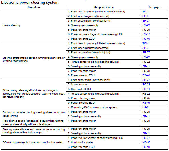
Use the table below to help determine the cause of the problem symptom. The potential causes of the symptoms are listed in order of probability in the "suspected area" column of the table. Check each symptom by checking the suspected areas in the order they are listed. Replace parts as necessary.
 How to proceed with troubleshooting
Hint:
Perform troubleshooting in accordance with the following
flowchart.
*: Use the intelligent tester.
Vehicle brought to workshop
Inspect battery voltage
Standard voltage:
11 ...
 Terminals of ecu
Check power steering ecu
Hint:
Measurements cannot be performed on the c connector
side of the power steering ecu.
Measure the voltage and resistance of the
connectors.
...
Other materials:
Fail-safe chart
Fail safe operation
If there is a problem with any sensor signals or
actuator systems, the skid control ecu prohibits the
power supply to the abs and traction actuator
and informs the ecm of vsc system failure.
The abs and traction actuator turns off the
solenoids and the ecm sh ...
How to proceed with troubleshooting
Hint:
Use the procedure to troubleshoot the power door lock
control system.
*: Use the intelligent tester.
Vehicle brought to workshop
Inspect battery voltage
Standard voltage:
11 to 14 v
If the voltage is below 11 v, recharge or replace the battery
before proceeding.
...
Ventilation valve
Components
Removal
Remove no. 1 Engine cover (see page em-22)
Remove ventilation valve sub-assembly
Disconnect the ventilation hose from the ventilation
valve.
Using a 22 mm deep socket wrench, remove the
ventilation valve.
Inspection
Inspect ventilation val ...
