Toyota RAV4 (XA40) 2013-2018 Service Manual: How to proceed with troubleshooting
Hint:
Perform troubleshooting in accordance with the following flowchart.
*: Use the intelligent tester.
- Vehicle brought to workshop

- Inspect battery voltage
Standard voltage: 11 to 14 v
If the voltage is below 11 v, recharge or replace the battery before proceeding.

- Problem symptom confirmation

- Check can communication system*
- Check for dtc (see page ps-11).
Result 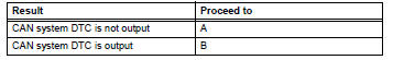
Hint:
- When any can communication system dtcs are output, perform troubleshooting on the can communication system first.
- When communication to the power steering ecu is not established through the intelligent tester, inspect terminals sil of the dlc3 and the power steering ecu, and the ig circuit of the power steering ecu.

- Check dtc*
- Check for dtc (see page ps-11).
Result 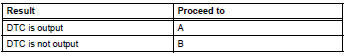

- Problem symptoms table
Result 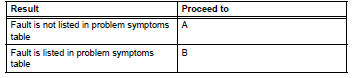


- Overall analysis and troubleshooting*
- Terminals of ecu (see page ps-8).
- Data list / active test (see page ps-14).

- Repair or replace

- Confirmation test

End
 System description
Description
The eps (electronic power steering) system generates
torque through the operation of the motor and the
reduction gear installed on the column shaft in order to
assist steering eff ...
 Problem symptoms table
Hint:
Use the table below to help determine the cause of the
problem symptom. The potential causes of the symptoms are
listed in order of probability in the "suspected area" column of
t ...
Other materials:
Safety information for children
Observe the following precautions when children are in the vehicle.
Use a child restraint system appropriate for the child, until the
child becomes large enough to properly wear the vehicle’s seat
belt.
It is recommended that children sit in the rear seats to avoid
accidental
contact ...
Correct driving posture
Adjust the angle of the seatback
so that you are sitting
straight up and so that you do
not have to lean forward to
steer.
Adjust the seat so that you can
depress the pedals fully and so
that your arms bend slightly at
the elbow when gripping the
steering wheel.
Lock the head ...
Rear wheel alignment
adjustment
Inspect tire
Inspect the tire (see page tw-1).
Measure vehicle height
Measure the vehicle height (see page sp-3).
Inspect toe-in
Standard toe-in
If the toe-in is not within the specified range, inspect the
suspension parts and replace them if necessar ...
