Toyota RAV4 (XA40) 2013-2018 Service Manual: Dtc check / clear
- Check dtc (using sst (check wire))
- Check the dtcs (present trouble code).
- Turn the ignition switch on, and wait for approximately 60 seconds.
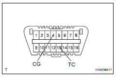
- Using sst, connect terminals 13(tc) and 4(cg) of the dlc3.
Sst 09843-18040
Notice:
Connect the terminals to the correct positions to avoid a malfunction.
- Check the dtcs (past trouble code)
- Using sst, connect terminals tc and 4(cg) of the dlc3.
Sst 09843-18040
Notice:
Connect the terminals to the correct positions to avoid a malfunction.
- Turn the ignition switch on, and wait for approximately 60 seconds.
- Read the dtcs.
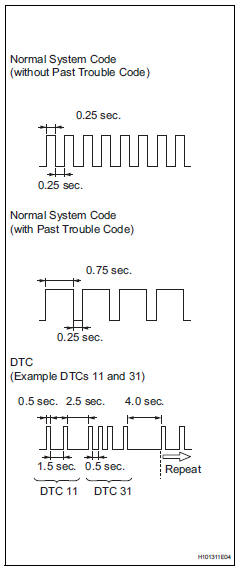
- Read the blinking patterns of the dtcs. As examples, the blinking patterns for the normal system code and dtcs 11 and 31 are shown in the illustration to the left.
- Normal system code indication (without past trouble code): the light blinks twice per second.
- Normal system code indication (with past trouble code): when the past trouble code is stored in the center airbag sensor, the light blinks only once per second.
- Trouble code indication: the first blinking indicates the first dtc. The second blinking occurs after a 1.5 Second pause.
If there is more than 1 code, there will be a 2.5 Second pause between each code. After all codes are shown, there will be a 4.0 Second pause, and then they all will be repeated.
Hint:
- If 2 or more malfunctions are found, the indication begins with the smaller numbered code.
- If dtcs are indicated without connecting the terminals, proceed to the "tc and cg terminal circuit" procedures (see page rs- 233).
- Clear dtc (using sst (check wire))
- Clear the dtcs.
- When the ignition switch is turned off, the dtcs are cleared.
Hint:
Depending on the dtc, the code may not be cleared by turning off the ignition switch. In this case, proceed to the next procedure.
- Using sst, connect terminals 13(13(tc)) and
4(cg) of the dlc3, and then turn the ignition
switch on.
Sst 09843-18040
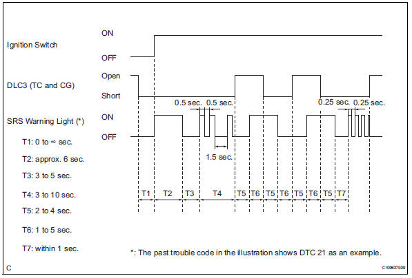
- Disconnect terminal 13(tc) of the dlc3 within 3 to 10 seconds after the dtcs are output, and check if the srs warning light comes on after 3 seconds.
- Within 2 to 4 seconds after the srs warning light comes on, connect terminals 13(tc) and 4(cg) of the dlc3.
- The srs warning light should go off within 2 to 4 seconds after connecting terminals 13(tc) and 4(cg) of the dlc3. Then, disconnect terminal 13(tc) within 2 to 4 seconds after the srs warning light goes off.
- The srs warning light comes on again within 2 to 4 seconds after disconnecting terminal 13(tc). Then, reconnect terminals 13(tc) and 4(cg) within 2 to 4 seconds after the srs warning light comes on.
- Check if the srs warning light goes off within 2
to 4 seconds after connecting terminals 13(tc)
and 4(cg) of the dlc3. Also check if the normal
system code is output within 1 second after the
srs warning light goes off.
If dtcs are not cleared, repeat this procedure until the codes are cleared.
- Check dtc (using intelligent tester)
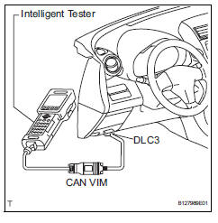
- Connect the intelligent tester (with can vim) to the dlc3.
- Turn the ignition switch on.
- Check the dtcs by following the prompts on the tester screen.
Hint:
Refer to the intelligent tester operator's manual for further details.
- Clear dtc (using intelligent tester)
- Connect the intelligent tester (with can vim) to the dlc3.
- Turn the ignition switch on.
- Clear the dtcs by following the prompts on the tester screen.
Hint:
Refer to the intelligent tester operator's manual for further details.
 Diagnosis system
Description
The center airbag sensor controls the functions of the
supplemental restraint system (srs) on the vehicle.
Data of the srs can be read in the data link connector
3 (dlc3) of the ...
 Check mode procedure
Check mode (signal check)
Connect the intelligent tester (with can vim) to the
dlc3.
Turn the ignition switch on.
Select the "signal check", and continue
checking with t ...
Other materials:
Compressor lock sensor circuit
Description
This sensor sends 1 pulse per engine revolution to the air conditioning
amplifier. If the ratio of the
compressor speed divided by the engine speed is smaller than a predetermined
value, the air conditioning
amplifier turns the compressor off, and the indicator blinks at appro ...
Rear window wiper
and washer
Turning the end of the lever turns on the rear window wiper, and pushing
the lever away from you turns on the rear window wiper and
washer.
For the u.S.A.
Intermittent operation
Normal operation
Washer/wiper dual operation
For Canada
Intermittent operation
Normal oper ...
Rear view monitor
system
The rear view monitor system assists the driver by displaying an
image of the view behind the vehicle and fixation guide lines
while backing up, for example while parking.
The screen illustrations used in this text are intended as examples,
and may differ from the image that is actually displaye ...
