Toyota RAV4 (XA40) 2013-2018 Service Manual: Compressor lock sensor circuit
![]()
Description
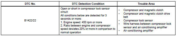
This sensor sends 1 pulse per engine revolution to the air conditioning amplifier. If the ratio of the compressor speed divided by the engine speed is smaller than a predetermined value, the air conditioning amplifier turns the compressor off, and the indicator blinks at approximately 1 second intervals.
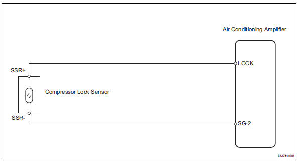
Wiring diagram
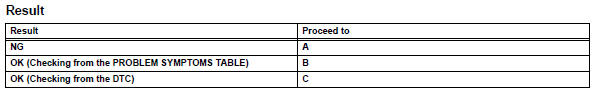
Inspection procedure
- Check air conditioning amplifier (lock signal)
- Remove the air conditioning amplifier with its connectors still connected.
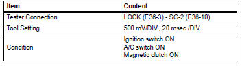
- Check the waveform of the amplifier connector.
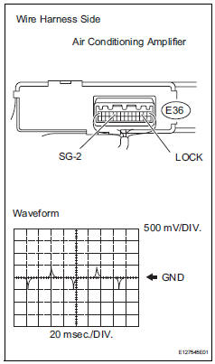
Ok:
waveform is as shown in the illustration.

- Inspect compressor lock sensor
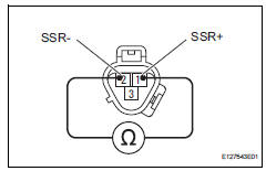
- Disconnect the b47 compressor lock sensor connector.
- Measure the resistance of the sensor.
Standard resistance 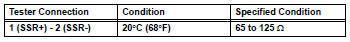

- Check wire harness (compressor lock sensor - air conditioning amplifier)
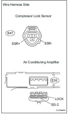
- Disconnect the b47 compressor lock sensor connector.
- Disconnect the e36 amplifier connector.
- Measure the resistance of the wire harness side connectors.
Standard resistance 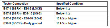

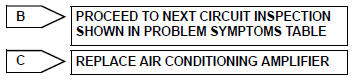
Replace air conditioning amplifier
 Evaporator temperature sensor circuit
Description
The no. 1 Cooler thermistor (evaporator temperature sensor) is installed on
the evaporator in the air
conditioning unit to detect the temperature of the cooled air that has passed ...
 Pressure sensor circuit
Description
This dtc is output when the refrigerant pressure is either extremely low
(0.19 Mpa [2.0 Kgf/cm2, 28 psi]
or less) or extremely high (3.14 Mpa [32.0 Kgf/cm2, 455 psi] or more). The ...
Other materials:
Differential oil
On-vehicle inspection
Check differential oil
Stop the vehicle on a level surface.
Using a 10 mm socket hexagon wrench, remove the
rear differential filler plug and gasket.
Check that the oil level is between 0 to 5 mm (0 to
0.20 In.) From the bottom lip of the different ...
Installation
Install drive plate sub-assembly
Clean the 8 bolts and 8 bolt holes.
Apply adhesive to 2 or 3 threads of the 8 bolts.
Adhesive:
Toyota genuine adhesive 1342, three bond
1342 or equivalent
Using sst, hold the crankshaft.
Sst 09213-54015 (91651-60855), 09330-00021
Instal ...
Driver side seat belt buckle switch circuit malfunction
Description
The driver side seat belt buckle switch circuit consists of the center airbag
sensor and the front seat inner
belt lh.
Dtc b1655/37 is recorded when a malfunction is detected in the driver side seat
belt buckle switch circuit.
Wiring diagram
Inspection procedure
...
