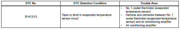
Toyota RAV4 (XA40) 2013-2018 Service Manual: Evaporator temperature sensor circuit
![]()
Description
The no. 1 Cooler thermistor (evaporator temperature sensor) is installed on the evaporator in the air conditioning unit to detect the temperature of the cooled air that has passed through the evaporator and to control the air conditioner. It sends signals to the air conditioning amplifier. The signals change in accordance with the resistance of the no. 1 Cooler thermistor (evaporator temperature sensor). As the temperature decreases, the resistance increases. As the temperature increases, the resistance decreases. The air conditioning amplifier applies a voltage (5 v) to the no. 1 Cooler thermistor (evaporator temperature sensor) and reads voltage changes as changes in the resistance of the no. 1 Cooler thermistor (evaporator temperature sensor). This sensor is used for frost prevention.
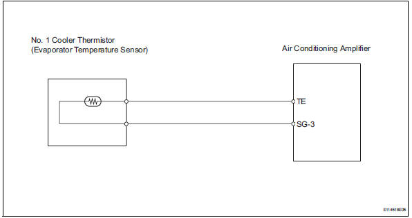
Wiring diagram
Inspection procedure
- Read value of intelligent tester (evap fin temp)
- Connect the intelligent tester (with can vim) to the dlc3.
- Turn the ignition switch on and turn the intelligent tester main switch on.
- Select the item below in the data list, and read the value displayed on the intelligent tester.
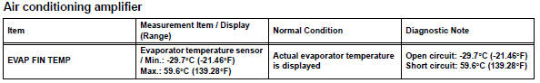
Ok: the display is as specified in the normal condition column.

- Inspect no. 1 Cooler thermistor (evaporator temperature sensor)
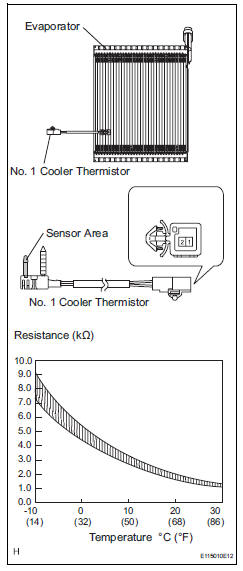
- Remove the no. 1 Cooler thermistor.
- Measure the resistance of the thermistor.
Standard resistance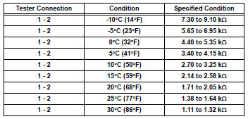
Notice:
- Touching the thermistor even slightly may change the resistance value. Be sure to hold the connector of the thermistor.
- When measuring, the thermistor temperature must be the same as the ambient temperature.
Hint:
As the temperature increases, the resistance decreases (see the graph).

- Check wire harness (no. 1 Cooler thermistor - air conditioning amplifier)
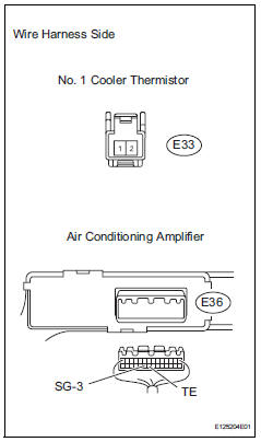
- Disconnect the e33 no. 1 Cooler thermistor connector.
- Disconnect the e36 amplifier connector.
- Measure the resistance of the wire harness side connectors.
Standard resistance 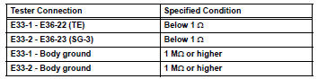

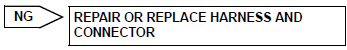
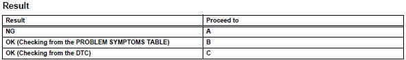
Replace air conditioning amplifier
 Ambient temperature sensor circuit
Description
The ambient temperature sensor is installed in the front part of the
condenser to detect the ambient
temperature and control the air conditioner. The sensor is connected to the
c ...
 Compressor lock sensor circuit
Description
This sensor sends 1 pulse per engine revolution to the air conditioning
amplifier. If the ratio of the
compressor speed divided by the engine speed is smaller than a predetermined ...
Other materials:
Brake warning light does not come on
Wiring diagram
Refer to the brake warning light circuit (see page bc-145).
Inspection procedure
Check can communication system
Check if the can communication system dtc is output
(see page ca-34).
Result
Perform active test by intelligent tester (brake warning light)
...
Diagnosis system
Description
Sliding roof system data and diagnostic trouble
codes (dtcs) can be read through the vehicle's
data link connector 3 (dlc3). When the system
seems to be malfunctioning, use the intelligent
tester to check for malfunctions and perform repairs.
Check dlc3
The vehi ...
If the vehicle becomes
stuck
Carry out the following procedures if the tires spin or the vehicle
becomes stuck in mud, dirt or snow:
Stop the engine. Set the parking brake and shift the shift lever to p.
Remove the mud, snow or sand from around the stuck tire.
Place wood, stones or some other material to help provide t ...
