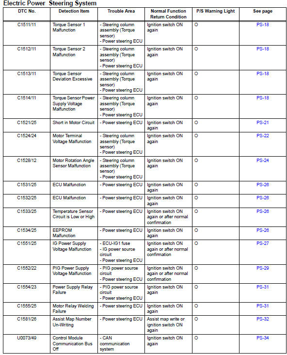
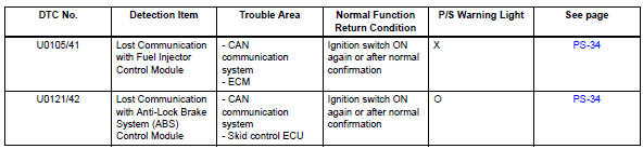
Toyota RAV4 (XA40) 2013-2018 Service Manual: Diagnostic trouble code chart
Hint:
If any dtcs are displayed during the dtc check, inspect the circuit listed for these dtcs. For details of each dtc, refer to the page indicated in the dtc chart.
Hint:
 : Warning
light comes on
X: warning light turns off (normal reset)
- Torque sensor
- Short in motor circuit
- Motor terminal voltage malfunction
- Motor rotation angle sensor malfunction
- Ecu malfunction
- Ig power supply voltage malfunction
- Pig power supply voltage malfunction
- Power supply relay failure
- Assist map number un-writing
- Control module communication bus off
- Eps warning light circuit
 Data list / active test
Read data list
Hint:
Using the intelligent tester's data list allows switch,
sensor, actuator and other item values to be read without
removing any parts. Reading the data list early in
trou ...
 Torque sensor
Description
The torque sensor converts the rotation torque input from the steering wheel
into electric signals and
sends them to the power steering ecu.
Wiring diagram
Inspection pro ...
Other materials:
Front power seat control system
Parts location
System diagram
Problem symptoms table
Hint:
Use the table below to help determine the cause of the
problem symptom. The potential causes of the symptoms are
listed in order of probability in the "suspected area" column
of the table. Check each symptom by check ...
Connecting a bluetooth®
device
Up to 5 bluetooth® devices (phones (hfp) and audio players
(avp)) can be registered.
If more than 1 bluetooth® device has been registered, select
which device to connect to.
Press the “setup” button.
Select “bluetooth*”.
*: Bluetooth is a registered trademark of bluetooth sig ...
Driving information display
Select to display fuel consumption
data in various forms.
â– Fuel Economy
Following information is displayed.
Distance to empty
Displays the driving range with
remaining fuel.
Current fuel economy
Displays the instantaneous current
fuel Economy.
Average fuel economy
Displays the average f ...
