Toyota RAV4 (XA40) 2013-2018 Service Manual: Problem symptoms table
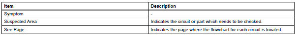
When a "normal" code is output during a dtc check but the problem is still occurring, use the problem symptoms table. The suspected areas (circuits or parts) for each problem symptom are in the table. The suspected areas are listed in order of probability. A description of each of the chart's columns is below.
Hint: in some cases, the problem is not detected by the diagnostic system even though a problem symptom is present. It is possible that the problem is occurring outside the detection range of the diagnostic system, or that the problem is occurring in a completely different system.
 Diagnostic trouble code chart
Look for output diagnostic trouble codes (dtcs) (from the
dtc checks) in the appropriate section's diagnostic trouble
code chart. Use the chart to determine the trouble area and
the proper inspecti ...
 Circuit inspection
A description of the main areas of each circuit inspection
is below.
Item
Description
description
The major role, operation of the circuit and its component parts are
explai ...
Other materials:
Releasing and stowing the seat belt (for the rear center seat)
To release the hooked buckle
“b”, push the buckle release
button.
Release button
To release the hooked plate
A insert the mechanical key
Or plate B or the
wireless key into the hole on
the buckle.
When releasing the seat belt,
retract it slowly.
Stow th ...
Multi-information display
Display contents
The multi-information display presents the driver with a variety of driving-
related data including the current outside air temperature.
Outside temperature display
Indicates the outside temperature.
The temperature range that can be
displayed is from -40„af (-40„ac) t ...
Cleaning the Digital Rearview
Mirror
â– Cleaning the mirror surface
If the mirror surface is dirty, the
image on the display may be difficult
to see.
Clean the mirror surface gently
using a soft dry cloth.
â– Cleaning the camera
If the camera lens is dirty, the
displayed image may not be
clear. In this case, clean it with a
soft clo ...
