Toyota RAV4 (XA40) 2013-2018 Service Manual: Rear drive shaft assembly
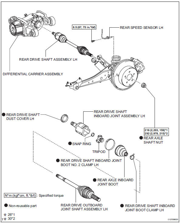
Components
Removal
Hint:
- Use the same procedures for the rh side and lh side.
- The procedures listed below are for the lh side.
- Disconnect cable from negative battery terminal
Caution:
Wait at least 90 seconds after disconnecting the cable from the negative (-) battery terminal to prevent airbag and seat belt pretensioner activation.
- Drain differential oil (see page df-10)
- Remove rear wheel
- Remove tailpipe assembly (see page ex-2)
- Remove center exhaust pipe assembly (see page ex-2)
- Remove propeller with center bearing shaft assembly (see page pr-3)
- Remove rear axle shaft nut (see page ah-17)
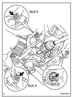
- Disconnect differential carrier assembly
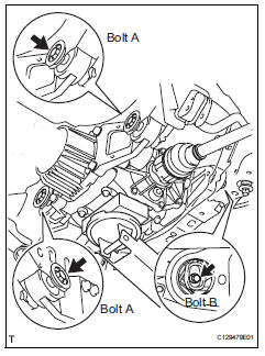
- Support the rear differential carrier with a transmission jack or equivalent.
- Fix the nuts in place and remove bolt a, bolt b and bolt c.
Notice:
Do not loosen the nuts. Loosen the bolts.
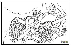
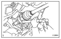
- Slowly lower the jack and then tilt the rear differential carrier as shown in the illustration.
- Set the tip of the tire lever to the position on the rear
drive shaft inboard joint shown in the illustration.
Then, using the ribbed part of the rear differential carrier as a fulcrum, disconnect the left and right rear drive shafts.
Notice:
Do not scratch the rear drive shaft dust cover.
- Disconnect skid control sensor wire (for 2wd) (see page bc-198)
- Disconnect rear speed sensor lh (for 4wd) (see page bc-205)
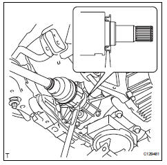
- Remove rear drive shaft assembly lh
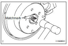
- Put matchmarks on the drive shaft and the axle hub.
Notice:
Do not punch the marks.
- Using a plastic-faced hammer, separate the drive shaft from the axle hub.
Notice:
Be careful not to damage the boot and speed sensor rotor. Do not excessively push out the drive shaft from the axle.
- Fix rear drive shaft assembly
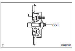
Notice:
The hub bearing could be damaged if it is subjected to the vehicle weight, such as when moving the vehicle with the drive shaft removed. Therefore, if it is absolutely necessary to place the vehicle weight on the hub bearing, first support it with sst.
Sst 09608-16042 (09608-02021, 09608-02041)
Disassembly
Hint:
- Use the same procedures for the rh side and lh side.
- The procedures listed below are for the lh side.
- Remove rear drive shaft inboard joint boot no. 2 Clamp lh
- Using needle-nose pliers, remove the inboard joint boot clamp, as shown in the illustration.
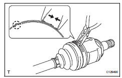
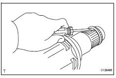
- Remove rear drive shaft inboard joint boot clamp lh
- Using needle-nose pliers, remove the inboard joint boot clamp, as shown in the illustration.
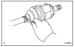
- Remove rear axle inboard joint boot
- Remove the boot from the inboard joint.
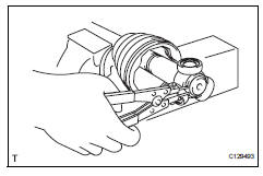
- Remove rear drive shaft inboard joint assembly lh
- Remove any old grease from the inboard joint.
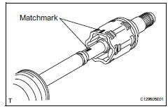
- Put matchmarks on the inboard joint and outboard joint shaft.
Notice:
Do not punch the marks.
- Remove the inboard joint from the outboard joint shaft.
- Using a snap ring expander, remove the shaft snap ring.
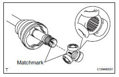
- Put matchmarks on the outboard joint shaft and tripod joint.
Notice:
Do not punch the marks.
- Using a brass bar and hammer, tap out the tripod joint from the outboard joint shaft.
Notice:
Do not tap the rollers.
- Remove the inboard joint boot.
- Remove rear drive shaft inboard joint lh shaft snap ring
- Using a screwdriver, remove the hole snap ring.
- Remove rear drive shaft dust cover lh
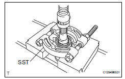
- Using sst and a press, press out the shaft dust cover.
Sst 09950-00020
Notice:
Be careful not to drop the inboard joint.
Reassembly
Hint:
- Use the same procedures for the rh side and lh side.
- The procedures listed below are for the lh side.
- Install rear drive shaft dust cover lh
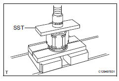
- Using sst and a press, press in a new drive shaft dust cover.
Sst 09527-10011
Notice:
- The dust cover should be installed completely.
- Be careful not to damage the dust cover.
- Install rear drive shaft inboard joint shaft snap ring lh
- Install a new hole snap ring.
- Install rear drive shaft inboard joint assembly lh
- Wrap the spline of the outboard joint shaft with vinyl tape to prevent the boots from being damaged.
- Install new parts to the outboard joint shaft in the following order.
- Inboard joint boot clamp
- No. 2 Inboard joint boot clamp
- Inboard joint boot
- Place the beveled side of the tripod axial spline toward the outboard joint.
- Align the matchmarks placed before removal.
- Using a brass bar and hammer, tap the tripod joint onto the drive shaft.
Notice:
- Do not tap the rollers.
- Be sure to install the tripod joint in the correct direction.
- Pack the inboard joint shaft and boot with grease from the boot kit.
Standard grease capacity: 86 to 96 g (3.0 To 3.4 Oz.)
- Using a snap ring expander, install a new shaft snap ring.
- Align the matchmarks, and install the inboard joint to the outboard joint shaft.
- Install rear axle inboard joint boot
- Install the inboard joint boot to the inboard joint.
- Install rear drive shaft inboard joint boot no. 2 Clamp lh
- Using needle-nose pliers, install the no. 2 Inboard joint boot clamp, as shown in the illustration.
Notice:
Be careful not to damage the boot.
- Install rear drive shaft inboard joint boot clamp lh
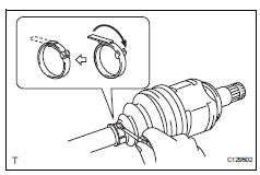
- Using a screwdriver, install the inboard joint boot clamp, as shown in the illustration.
Notice:
Be careful not to damage the boot.
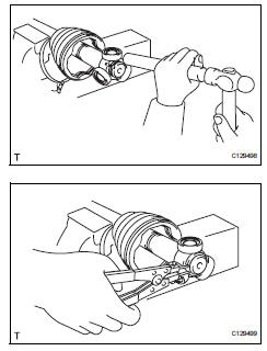
- Inspect rear drive shaft
- Check that there is no severe play in the radial direction of the outboard joint.
- Check that the inboard joint slides smoothly in the thrust direction.
- Check that there is no severe play in the radial direction of the inboard joint.
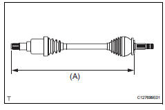
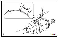
- Check the boots for damage.
Notice:
Keep the drive shaft assembly level during inspection.
Hint:
For dimension (a), refer to the following values.
Reference value: 733.8 Mm (28.890 In.)
Installation
Hint:
- Use the same procedures for the rh side and lh side.
- The procedures listed below are for the lh side.
- Install rear drive shaft assembly lh
- Align the splines of the rear drive shaft outboard joints and, install the left and right rear drive shafts to the axle hub.
- Install differential carrier assembly
- Apply hypoid gear oil to the splines of the left and right rear drive shaft inboard joints.
- Align the splines of the rear drive shaft inboard joints and, using a brass bar and hammer, tap in the left and right rear drive shafts.
Notice:
- Face the cutout section of the snap ring downward.
- Do not damage the oil seal during the insertion.
- Do not strike the tip of the outboard joint with the hammer.
Hint:
Determine whether or not the rear drive shaft is completely tapped in by checking for changes in sound or the reaction force of the brass bar
- Slowly raise the transmission jack, fix the nuts in place and install the 3 bolts.
Torque: 86 n*m (877 kgf*cm, 63 ft.*Lbf) for bolt a 140 n*m (1,428 kgf*cm, 103 ft.*Lbf) for bolt b
Notice:
Tighten the bolts, not the nuts.
- Install skid control sensor wire (for 2wd) (see page bc-201)
- Install rear speed sensor lh (for 4wd) (see page bc-206)
- Install rear axle shaft nut (see page ah-18)
- Temporarily install propeller with center bearing shaft assembly (see page pr-5)
- Tighten propeller with center bearing shaft assembly (see page pr-6)
- Inspect and adjust joint angle (see page pr- 4)
- Install center exhaust pipe assembly (see page ex-5)
- Install tailpipe assembly (see page ex-6)
- Install rear wheel torque: 103 n*m (1,050 kgf*cm, 76 ft.*Lbf)
- Add differential oil (see page df-3)
- Connect cable to negative battery terminal
Notice:
When the warning light is illuminated or the battery has been disconnected and reconnected, turning the power switch may not start the system on the first try. If so, turn the power switch again.
- Check for differential oil leakage
- Check for exhaust gas leakage
If gas is leaking, tighten the areas necessary to stop the leak. Replace damaged parts as necessary.
- Inspect rear wheel alignment
- Inspect the rear wheel alignment (see page sp-7).
 Installation (2006/01- )
Install front drive shaft assembly lh
Coat the spline of the inboard joint shaft with gear
oil.
Align the shaft splines and tap in the drive shaft with
a brass bar and hammer.
No ...
 Axle
Axle
...
Other materials:
Installation
Hint:
Use the same procedures for the rh side and lh side.
The procedures listed below are for the lh side.
When replacing the clip, heat the clip and body using a
heat light.
Standard heating temperature
Notice:
Do not heat the clip and vehicle body excessively.
Replace roof dri ...
Short in front driver side - side squib circuit
Description
The driver side - side squib circuit consists of the center airbag sensor and
the front seat side airbag lh.
This circuit instructs the srs to deploy when the deployment conditions are met.
These dtcs are recorded when a malfunction is detected in the driver side - side
sq ...
For vehicles equipped with vehicle stability (vsc) system
Notices when using drum tester
Before beginning testing, disable the vsc. To
disable the vsc, turn the ignition switch off
and connect sst to terminals 12 (ts) and 4
(cg) of the dlc3.
Sst 09843-18040
Notice:
Confirm that the vsc warning light blinks.
Vsc system will be r ...
