Toyota RAV4 (XA40) 2013-2018 Service Manual: Room light assembly
Components
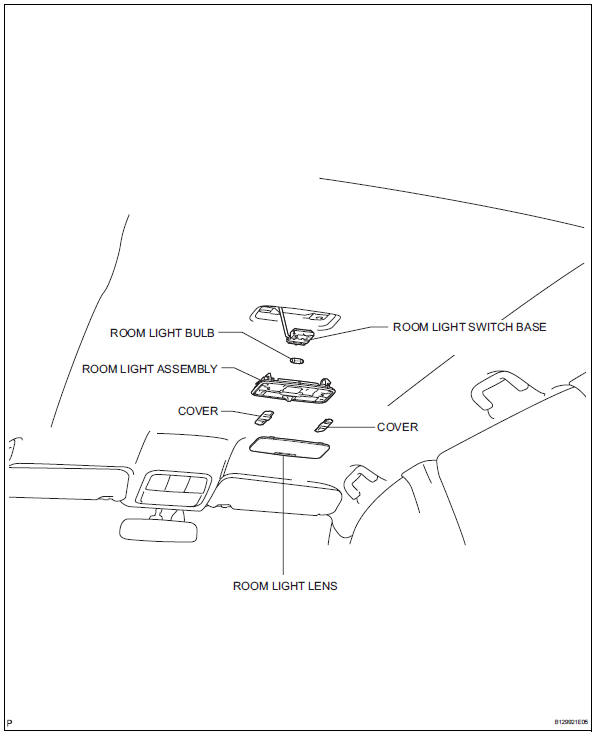
Removal
- Disconnect cable from negative battery terminal
Caution:
Wait at least 90 seconds after disconnecting the cable from the negative (-) battery terminal to prevent airbag and seat belt pretensioner activation.
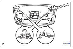
- Remove room light lens
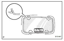
- Using a screwdriver, detach the 4 claws and remove the lens.
Hint:
Tape the screwdriver tip before use.
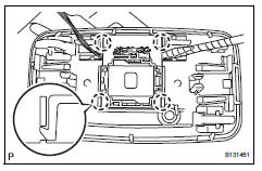
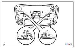
- Remove room light assembly
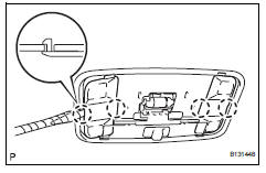
- Using a screwdriver, detach the 4 claws and remove the 2 covers.
Hint:
Tape the screwdriver tip before use.
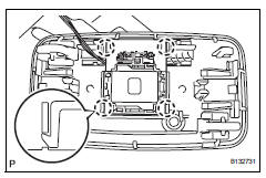
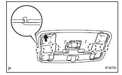
- Remove the bulb from the room light switch base.
- Using a screwdriver, detach the 4 claws and remove the light.
Hint:
Tape the screwdriver tip before use.
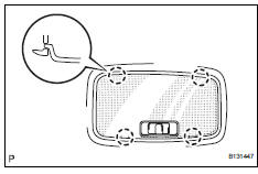
- Using a screwdriver, detach the 4 claws and remove the room light switch base.
Hint:
Tape the screwdriver tip before use.
Inspection
- Inspect room light
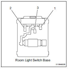
- Connect the battery's positive (+) lead to terminal 1 and the negative (-) lead to terminal 2, and then check that the light comes on when the switch is in the door position.
Ok: light comes on.
If the result is not as specified, replace the light assembly.
- Connect the positive (+) lead from the battery to terminal 1 and the negative (-) lead to terminal 3, then check that the light comes on when the switch is in the on position.
Ok: light comes on.
If the result is not as specified, replace the light assembly.
Installation
- Install room light assembly
- Attach the 4 claws to install the room light switch base.
- Attach the 4 claws to install the room light.
- Install the bulb to the room light switch base.
- Attach the 4 claws to install the 2 covers.
- Install room light lens
- Attach the 4 claws to install the lens.
- Connect cable to negative battery terminal
 Map light assembly
Components
Removal
Disconnect cable from negative battery
terminal
Caution:
Wait at least 90 seconds after disconnecting the
cable from the negative (-) battery terminal to
prevent ai ...
 Luggage room light
Components
Removal
Disconnect cable from negative battery
terminal
Caution:
Wait at least 90 seconds after disconnecting the
cable from the negative (-) battery terminal to
prevent ai ...
Other materials:
Operation check
Illuminated entry system operation check
The illuminated entry system controls the following
lights:
Ignition key cylinder light*1 or transponder key
amplifier*2
Foot light
Map light and room light
Hint:
*1: W/o engine immobiliser system
*2: W/ engine immobiliser ...
Ecm / pcm internal engine off timer performance
Dtc summary
Description
To ensure the accuracy of the evap (evaporative emission) monitor values, the
soak timer, which is built
into the ecm, measures 5 hours (+-15 minutes) from when the ignition switch is
turned off, before the
monitor is run. This allows the fuel to cool down, wh ...
Repair
Repair valve seats
If the seating is too high on the valve face, use 30°
and 45° cutters to correct the seat.
If the seating is too low on the valve face, use 75°
and 45° cutters to correct the seat.
Standard width
Lap the valve and valve seat by hand with an
abrasiv ...
