Toyota RAV4 (XA40) 2013-2018 Service Manual: Installation (2005/11-2006/01)
- Install front drive shaft assembly lh
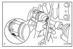
- Coat the spline of the inboard joint shaft with gear oil.
- Using a brass bar and hammer, align the shaft splines in the drive shaft.
Notice:
- Set the snap ring with the opening side facing downwards.
- Be careful not to damage the oil seal, boot and dust cover.
- Install front drive shaft assembly rh
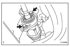
- Coat the spline of the inboard joint shaft with gear oil.
- Align the shaft spline and install the drive shaft with 2 bolts.
Torque: 63.7 N*m (650 kgf*cm, 47 ft.*Lbf)
Notice:
Do not damage the oil seal, boot and dust cover.
- Connect steering knuckle with axle hub lh
- Align the shaft splines in the drive shaft to the steering knuckle with axle hub.
- Connect steering knuckle with axle hub rh
Hint:
Use the same procedures described for the lh side.
- Connect front suspension no. 1 Lower arm sub-assembly lh (see page ah-10)
- Connect front suspension no. 1 Lower arm sub-assembly rh
Hint:
Use the same procedures described for the lh side.
- Install front stabilizer link assembly lh (see page sp-31)
- Install front stabilizer link assembly rh
Hint:
Use the same procedures described for the lh side.
- Connect tie rod end sub-assembly lh (see page ps-45)
- Connect tie rod end sub-assembly rh
Hint:
Use the same procedures described for the lh side.
- Connect front speed sensor lh
- Connect the speed sensor (see page bc-191).
- Connect front speed sensor rh
Hint:
Use the same procedures described for the lh side.
- Install front axle hub nut (see page ah-10)
- Install front wheel torque: 103 n*m (1,050 kgf*cm, 76 ft.*Lbf)
- Add automatic transaxle fluid
- Add automatic transaxle fluid for u140f (see page ax-152).
- Add automatic transaxle fluid for u241e (see page ax-151).
- Check for automatic transaxle oil leakage
- Inspect and adjust front wheel alignment
- Inspect and adjust the front wheel alignment (see page sp-3).
 Reassembly (2006/01- )
Install drive shaft bearing case subassembly
(for rh)
Install the bearing snap ring.
Using sst and a press, press in the drive shaft
bearing case to the inboard joint rh.
Sst 095 ...
 Installation (2006/01- )
Install front drive shaft assembly lh
Coat the spline of the inboard joint shaft with gear
oil.
Align the shaft splines and tap in the drive shaft with
a brass bar and hammer.
No ...
Other materials:
Headlight relay circuit
Description
When the light control switch, located on the headlight dimmer switch, is
turned to the head position, the
head relay illuminates the headlights.
Wiring diagram
Inspection procedure
Perform active test by intelligent tester (headlight)
Connect the intelligent tester ( ...
Removal
Discharge refrigerant from
refrigeration system (see page ac-172)
Disconnect cable from negative battery
terminal
Caution:
Wait at least 90 seconds after disconnecting the
cable from the negative (-) battery terminal to
prevent airbag and seat belt pretensioner activation.
Remove ...
Abs and traction actuator (skid control ecu) communication stop mode
Description
Wiring diagram
Inspection procedure
Notice:
Turn the ignition switch off before measuring the resistances
of the main wire and the branch
wire.
After the ignition switch is turned off, check that the key
reminder warning system and light
reminder warning system ...
