Toyota RAV4 (XA40) 2013-2018 Service Manual: Installation (2006/01- )
- Install front drive shaft assembly lh
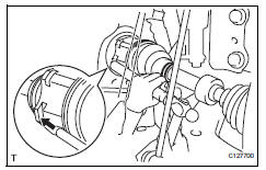
- Coat the spline of the inboard joint shaft with gear oil.
- Align the shaft splines and tap in the drive shaft with a brass bar and hammer.
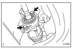
Notice:
- Set the snap ring with the opening side facing downwards.
- Be careful not to damage the oil seal, boot and dust cover.
- Install front drive shaft assembly rh
- Coat the spline of the inboard joint shaft with gear oil.
- Align the shaft splines and securely insert the drive shaft.
- Install the 2 bearing bracket bolts.
Torque: 63.7 N*m (650 kgf*cm, 47 ft.*Lbf)
Notice:
Do not damage the oil seal, boot and dust cover.
- Connect steering knuckle with axle hub lh
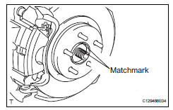
- Align the shaft splines in the drive shaft to the steering knuckle with axle hub, and connect the steering knuckle with axle hub.
- Connect steering knuckle with axle hub rh
Hint:
Use the same procedures described for the lh side.
- Connect front suspension no. 1 Lower arm sub-assembly lh (see page sp-24)
- Connect front suspension no. 1 Lower arm sub-assembly rh
Hint:
Use the same procedures described for the lh side.
- Install front stabilizer link assembly lh (see page sp-31)
- Install front stabilizer link assembly rh
Hint:
Use the same procedures described for the lh side.
- Connect tie rod end sub-assembly lh (see page ps-45)
- Connect tie rod end sub-assembly rh
Hint:
Use the same procedures described for the lh side.
- Connect front speed sensor lh
- Connect the speed sensor (see page bc-193).
- Install front speed sensor rh
Hint:
Use the same procedures described for the lh side.
- Install front axle hub nut (see page ah-11)
- Install front wheel torque: 103 n*m (1,050 kgf*cm, 76 ft.*Lbf)
- Add automatic transaxle fluid
- Add automatic transaxle fluid for u140f (see page ax-152).
- Add automatic transaxle fluid for u241e (see page ax-151).
- Add automatic transaxle fluid for u151e (see page ax-177).
- Check for automatic transaxle oil leakage
- Inspect and adjust front wheel alignment
- Inspect and adjust the front wheel alignment (see page sp-3).
 Installation (2005/11-2006/01)
Install front drive shaft assembly lh
Coat the spline of the inboard joint shaft with gear
oil.
Using a brass bar and hammer, align the shaft
splines in the drive shaft.
Notice:
...
 Front drive shaft assembly (for 4wd)
Components (2005/11-2006/01)
Components (2006/01- )
...
Other materials:
Rear upper control arm
Components
Removal
Hint:
Use the same procedures for the rh side and lh side.
The procedures listed below are for the lh side.
Remove rear wheel
Disconnect skid control sensor wire (for
2wd) (see page bc-198)
Disconnect rear speed sensor lh (for 4wd)
(see page bc-205)
Rem ...
Oxygen sensor circuit
Description
In order to obtain a high purification rate of the carbon monoxide (co),
hydrocarbon (hc) and nitrogen
oxide (nox) components in the exhaust gas, a twc is used. For the most efficient
use of the twc, the
air-fuel ratio must be precisely controlled so that it is always close to ...
Snow mode switch (AWD
vehicles)
Snow mode can be selected
to suit the conditions when
driving on slippery road surfaces,
such as on snow.
System operation
â– Dynamic Torque Control
AWD vehicles
Press the snow mode switch.
When the switch is pressed, the
system switches to snow mode and
the snow mode indicator illuminates
on the ...
