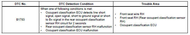
Toyota RAV4 (XA40) 2013-2018 Service Manual: Rear occupant classification sensor rh circuit malfunction

Description
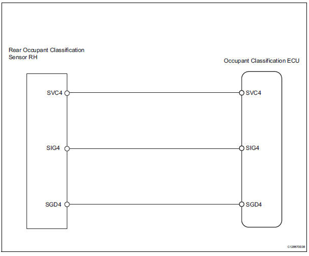
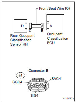
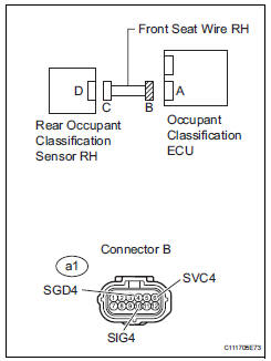
The rear occupant classification sensor rh circuit consists of the occupant classification ecu and the rear occupant classification sensor rh.
Dtc b1783 is recorded when a malfunction is detected in the rear occupant classification sensor rh circuit.
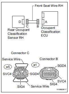
Wiring diagram
Inspection procedure
Hint:
- If troubleshooting (wire harness inspection) is difficult to perform, remove the front passenger seat installation bolts to see the undersurface of the seat cushion.
- In the above case, hold the seat so that it does not tip over. Holding the seat for a long period of time may cause a problem, such as seat rail deformation. Hold the seat up only for as long as necessary.
- Check dtc
- Turn the ignition switch on.
- Clear the dtcs (see page rs-249).
Hint:
First clear dtcs stored in the occupant classification ecu and then in the center airbag sensor.
- Turn the ignition switch off.
- Turn the ignition switch on.
- Check the dtcs (see page rs-249).
Ok: dtc b1783 is not output.
Hint:
Dtcs other than dtc b1783 may be output at this time, but they are not related to this check.

- Check connection of connector
- Turn the ignition switch off.
- Disconnect the cable from the negative (-) battery terminal, and wait for at least 90 seconds.
- Check that the connectors are properly connected to the occupant classification ecu and the rear occupant classification sensor rh.
Ok: the connectors are properly connected.

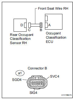
- Check front seat wire rh (to b+)
- Disconnect the connectors from the occupant classification ecu and the rear occupant classification sensor rh.
- Connect the cable to the negative (-) battery terminal, and wait for at least 2 seconds.
- Turn the ignition switch on.
- Measure the voltage of the wire harness side connector.
Standard voltage 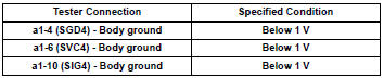

- Check front seat wire rh (for open)
- Turn the ignition switch off.
- Disconnect the cable from the negative (-) battery terminal, and wait for at least 90 seconds.
- Using a service wire, connect terminals a5-1 (svc4) and a5-3 (sgd4), and connect terminals a5-2 (sig4) and a5- 3 (sgd4) of connector c.
Notice:
Do not forcibly insert a service wire into the terminals of the connector when connecting them.
- Measure the resistance of the wire harness side connector.
Standard resistance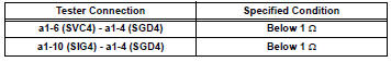

- Check front seat wire rh (for short)
- Disconnect the service wire from connector c.
- Measure the resistance of the wire harness side connector.
Standard resistance 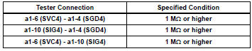

- Check front seat wire rh (to ground)
- Measure the resistance of the wire harness side connector.
Standard resistance 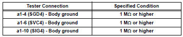

- Check for dtc
- Connect the connectors to the occupant classification ecu and the rear occupant classification sensor rh.
- Connect the cable to the negative (-) battery terminal, and wait for at least 2 seconds.
- Turn the ignition switch on.
- Clear the dtcs (see page rs-249).
Hint:
First clear dtcs stored in the occupant classification ecu and then in the center airbag sensor.
- Turn the ignition switch off.
- Turn the ignition switch on.
- Check the dtcs (see page rs-249).
Ok: dtc b1783 is not output.
Hint
Dtcs other than dtc b1783 may be output at this time, but they are not related to this check.

- Replace occupant classification ecu
- Turn the ignition switch off.
- Disconnect the cable from the negative (-) battery terminal, and wait for at least 90 seconds.
- Replace the occupant classification ecu (see page rs- 392).
Hint:
Perform the inspection using parts from a normal vehicle if possible.

- Perform zero point calibration
- Connect the cable to the negative (-) battery terminal, and wait for at least 2 seconds.
- Connect the intelligent tester to the dlc3.
- Turn the ignition switch on.
- Using the intelligent tester, perform the zero point calibration (see page rs-241).
Ok: completed is displayed.

- Perform sensitivity check
- Using the intelligent tester, perform the sensitivity check (see page rs-241).
Standard value: 27 to 33 kg (59.52 To 72.75 Lb)

- Check for dtc
- Connect the cable to the negative (-) battery terminal, and wait for at least 2 seconds.
- Turn the ignition switch on.
- Clear the dtcs (see page rs-249).
Hint:
First clear dtcs stored in the occupant classification ecu and then in the center airbag sensor.
- Turn the ignition switch off.
- Turn the ignition switch on.
- Check the dtcs (see page rs-249).
Ok: dtc b1783 is not output.
Hint:
Dtcs other than dtc b1783 may be output at this time, but they are not related to this check.


Replace front seat assembly rh
- Turn the ignition switch off.
- Disconnect the cable from the negative (-) battery terminal, and wait for at least 90 seconds
- Replace the front seat rh (see page se-8).

- Perform zero point calibration
- Connect the cable to the negative (-) battery terminal, and wait for at least 2 seconds.
- Connect the intelligent tester to the dlc3.
- Turn the ignition switch on.
- Using the intelligent tester, perform the zero point calibration (see page rs-241).
Ok: completed is displayed.

- Perform sensitivity check
- Using the intelligent tester, perform the sensitivity check (see page rs-241).
Standard value: 27 to 33 kg (59.52 To 72.75 Lb)

End
 Rear occupant classification sensor lh circuit malfunction
Description
The rear occupant classification sensor lh circuit consists of the occupant
classification ecu and the rear
occupant classification sensor lh.
Dtc b1782 is recorded when a malf ...
 Front occupant classification sensor lh collision detection
Description
Dtc b1785 is output when the occupant classification ecu receives a collision
detection signal sent by
the front occupant classification sensor lh when an accident occurs.
Dtc b ...
Other materials:
Compressor circuit
Description
When the a/c switch is turned on, the magnetic clutch on signal is sent from
the air conditioning
amplifier. Then the mg clt relay turns on to operate the magnetic clutch.
Wiring diagram
Inspection procedure
Perform active test by intelligent tester (a/c mag clutch)
C ...
Reassembly
Install generator rotor assembly
Install the washer onto the generator rectifier end
frame.
Install the generator rotor onto the generator
rectifier end frame.
Using a 32 mm socket wrench and press, slowly
push the generator drive end frame onto the
generator ...
Body
General maintenance
Tighten bolts and nuts
Tighten the bolts and nuts on the chassis parts listed
below, if necessary.
Front axle and suspension
Drivetrain
Rear axle and suspension
Brake system
Engine mounting
Other chassis parts
Tighten the bolts and nuts on the bo ...
