Toyota RAV4 (XA40) 2013-2018 Service Manual: Rear occupant classification sensor lh circuit malfunction

Description
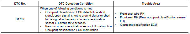
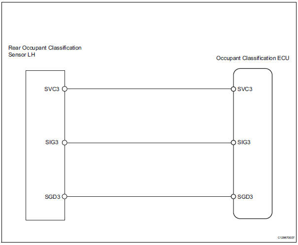
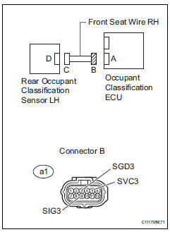
The rear occupant classification sensor lh circuit consists of the occupant classification ecu and the rear occupant classification sensor lh.
Dtc b1782 is recorded when a malfunction is detected in the rear occupant classification sensor lh circuit.
Wiring diagram
Inspection procedure
Hint:
- If troubleshooting (wire harness inspection) is difficult to perform, remove the front passenger seat installation bolts to see the undersurface of the seat cushion.
- In the above case, hold the seat so that it does not tip over. Holding the seat for a long period of time may cause a problem, such as seat rail deformation. Hold the seat up only for as long as necessary.
- Check for dtc
- Turn the ignition switch on.
- Clear the dtcs (see page rs-249).
Hint:
First clear dtcs stored in the occupant classification ecu and then in the center airbag sensor.
- Turn the ignition switch off.
- Turn the ignition switch on.
- Check the dtcs (see page rs-249).
Ok: dtc b1782 is not output.
Hint:
Dtcs other than dtc b1782 may be output at this time, but they are not related to this check.

- Check connection of connector
- Turn the ignition switch off.
- Disconnect the cable from the negative (-) battery terminal, and wait for at least 90 seconds.
- Check that the connectors are properly connected to the occupant classification ecu and the rear occupant classification sensor lh.
Ok: the connectors are properly connected.

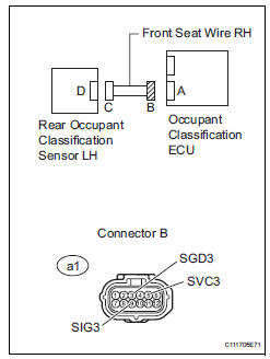
- Check front seat wire rh (to b+)
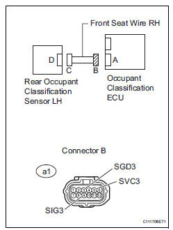
- Disconnect the connectors from the occupant classification ecu and the rear occupant classification sensor lh.
- Connect the cable to the negative (-) battery terminal, and wait for at least 2 seconds.
- Turn the ignition switch on.
- Measure the voltage of the wire harness side connector.
Standard voltage 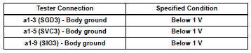

- Check front seat wire rh (for open)
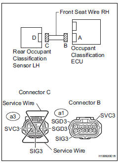
- Turn the ignition switch off.
- Disconnect the cable from the negative (-) battery terminal, and wait for at least 90 seconds.
- Using a service wire, connect terminals a3-1 (svc3) and a3-3 (sgd3), and connect terminals a3-2 (sig3) and a3- 3 (sgd3) of connector c.
Notice:
Do not forcibly insert a service wire into the terminals of the connector when connecting them.
- Measure the resistance of the wire harness side connector.
Standard resistance 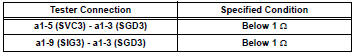

- Check front seat wire rh (for short)
- Disconnect the service wire from connector c.
- Measure the resistance of the wire harness side connector.
Standard resistance 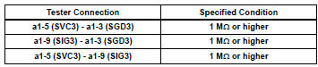

- Check front seat wire rh (to ground)
- Measure the resistance of the wire harness side connector.
Standard resistance 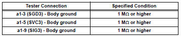

- Check for dtc
- Connect the connectors to the occupant classification ecu and the rear occupant classification sensor lh.
- Connect the cable to the negative (-) battery terminal, and wait for at least 2 seconds.
- Turn the ignition switch on.
- Clear the dtcs (see page rs-249).
Hint:
First clear dtcs stored in the occupant classification ecu and then in the center airbag sensor.
- Turn the ignition switch off.
- Turn the ignition switch on.
- Check the dtcs (see page rs-249).
Ok: dtc b1782 is not output.
Hint:
Dtcs other than dtc b1782 may be output at this time, but they are not related to this check.

- Replace occupant classification ecu
- Turn the ignition switch off.
- Disconnect the cable from the negative (-) battery terminal, and wait for at least 90 seconds.
- Replace the occupant classification ecu (see page rs- 392).
Hint:
Perform the inspection using parts from a normal vehicle if possible.

- Perform zero point calibration
- Connect the cable to the negative (-) battery terminal, and wait for at least 2 seconds.
- Connect the intelligent tester to the dlc3.
- Turn the ignition switch on.
- Using the intelligent tester, perform the zero point calibration (see page rs-241).
Ok: completed is displayed.


- Perform sensitivity check
- Using the intelligent tester, perform the sensitivity check (see page rs-241).
Standard value: 27 to 33 kg (59.52 To 72.75 Lb)


- Check for dtc
- Connect the cable to the negative (-) battery terminal, and wait for at least 2 seconds.
- Turn the ignition switch on.
- Clear the dtcs (see page rs-249).
Hint:
First clear dtcs stored in the occupant classification ecu and then in the center airbag sensor.
- Turn the ignition switch off.
- Turn the ignition switch on.
- Check the dtcs (see page rs-249).
Ok: dtc b1782 is not output.
Hint:
Dtcs other than dtc b1782 may be output at this time, but they are not related to this check.

- Replace front seat assembly rh
- Turn the ignition switch off.
- Disconnect the cable from the negative (-) battery terminal, and wait for at least 90 seconds.
- Replace the front seat assembly rh (see page se-8).

- Perform zero point calibration
- Connect the negative (-) terminal cable to the battery, and wait for at least 2 seconds.
- Connect the intelligent tester to the dlc3.
- Turn the ignition switch on.
- Using the intelligent tester, perform the zero point calibration (see page rs-241).
Ok: completed is displayed.

- Perform sensitivity check
- Using the intelligent tester, perform the sensitivity check (see page rs-241).
Standard value: 27 to 33 kg (59.52 To 72.75 Lb)

End
 Front occupant classification sensor rh circuit malfunction
Description
The front occupant classification sensor rh circuit consists of the occupant
classification ecu and the
front occupant classification sensor rh.
Dtc b1781 is recorded when a mal ...
 Rear occupant classification sensor rh circuit malfunction
Description
The rear occupant classification sensor rh circuit consists of the occupant
classification ecu and the
rear occupant classification sensor rh.
Dtc b1783 is recorded when a malf ...
Other materials:
Heated oxygen sensor
Components
Removal
Disconnect cable from negative battery
terminal
Caution:
Wait at least 90 seconds after disconnecting the
cable from the negative (-) battery terminal to
prevent airbag and seat belt pretensioner activation.
Remove heated oxygen sensor (for bank 1 sensor 2)
...
Speaking on the phone
The following screen is displayed when speaking on the phone.
To adjust the call volume
Select “-” or “+”. You can also adjust the volume using the steering
switches or the volume knob.
To prevent the other party from hearing your voice
Select “mute”.
Inputting tones
When usin ...
Removal
Discharge fuel system pressure (see page
fu-9)
Drain coolant (see page co-6)
Disconnect cable from negative battery
terminal
Caution:
Wait at least 90 seconds after disconnecting the
cable from the negative (-) battery terminal to
prevent airbag and seat belt pretensioner activation ...
