Toyota RAV4 (XA40) 2013-2018 Service Manual: Terminals of ecu (2005/11-2006/01)
Notice:
- Turn the ignition switch off before measuring the resistances of the main wire and the branch wire.
- After the ignition switch is turned off, check that the key reminder warning system and light reminder warning system are not in operation.
- Before measuring the resistance, leave the vehicle for at least 1 minute and do not operate the ignition switch, any switches or doors. If doors need to be opened in order to check connectors, open the doors and leave them open.
Hint:
Operating the ignition switch, any switches or any doors triggers related ecu and sensor communication with the can, which causes resistance variation.
- Junction connector
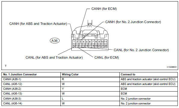
- No. 1 Junction connector
-
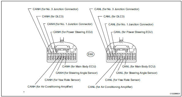
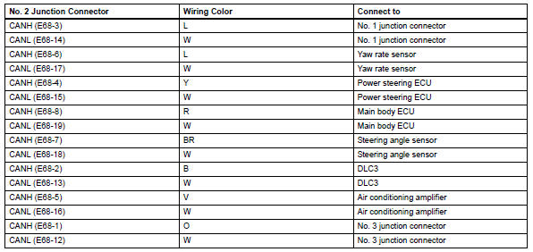
No. 2 Junction connector
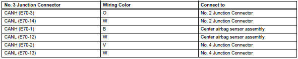
- No. 3 Junction connector
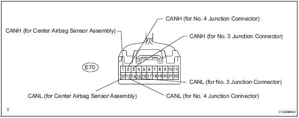
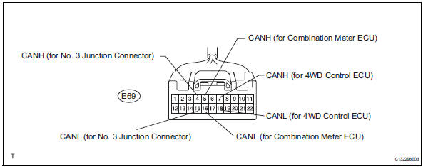
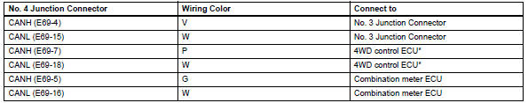
- No. 4 Junction connector
Hint:
*: For 4wd
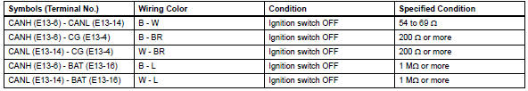
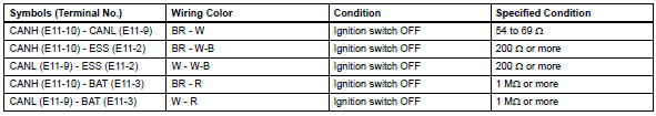
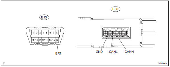
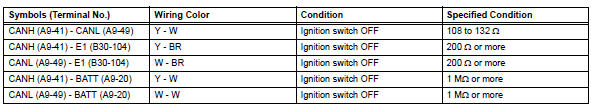
- Check dlc3
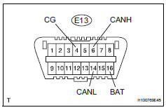
- Measure the resistance of the connector.
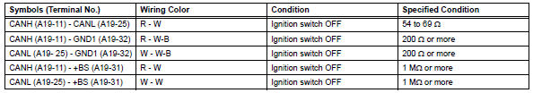
- Check abs and traction actuator (skid control ecu)
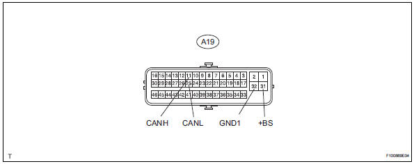
- Disconnect the a19 ecu connector.
- Measure the resistance of the wire harness side connector.
- Check steering angle sensor
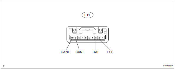
- Disconnect the e11 sensor connector.
- Measure the resistance of the wire harness side connector.
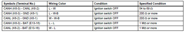
- Check yaw rate sensor
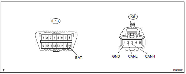
- Disconnect the k6 sensor connector.
- Measure the resistance of the wire harness side connector.
- Check air conditioning amplifier (for automatic air conditioning system)
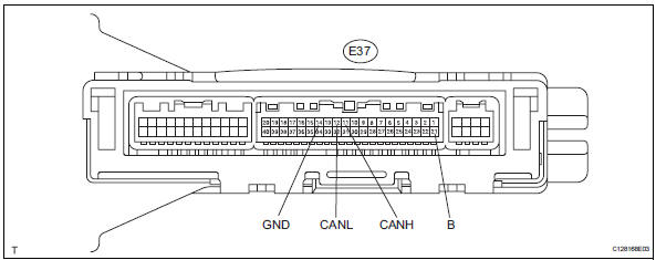
- Disconnect the e37 amplifier connector.
- Measure the resistance of the wire harness side connector.
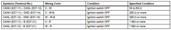
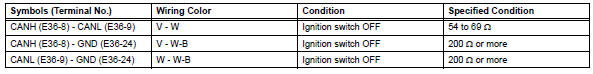
- Check air conditioning amplifier (for manual air conditioning system)
- Disconnect the e36 amplifier connector.
- Measure the resistance of the wire harness side connector.

- Check ecm
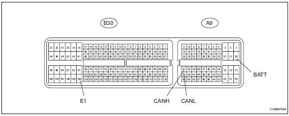
- Disconnect the a19 and b30 ecm connectors.
- Measure the resistance of the wire harness side connectors.
- Check center airbag sensor assembly
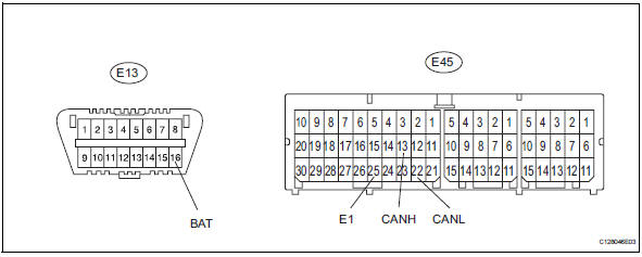
- Disconnect the e45 sensor connector.
- Measure the resistance of the wire harness side connectors.

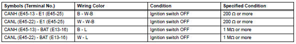
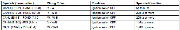
- Check power steering ecu
- Disconnect the a1 and e18 ecu connectors.
- Measure the resistance of the wire harness side connectors.
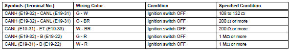
- Check combination meter ecu
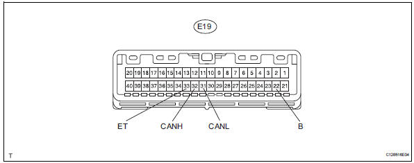
- Disconnect the e19 ecu connector.
- Measure the resistance of the wire harness side connector.
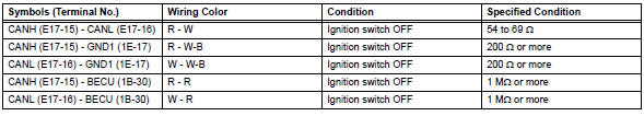
- Check instrument panel junction block (main body ecu)
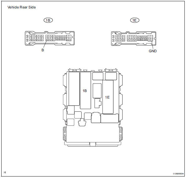
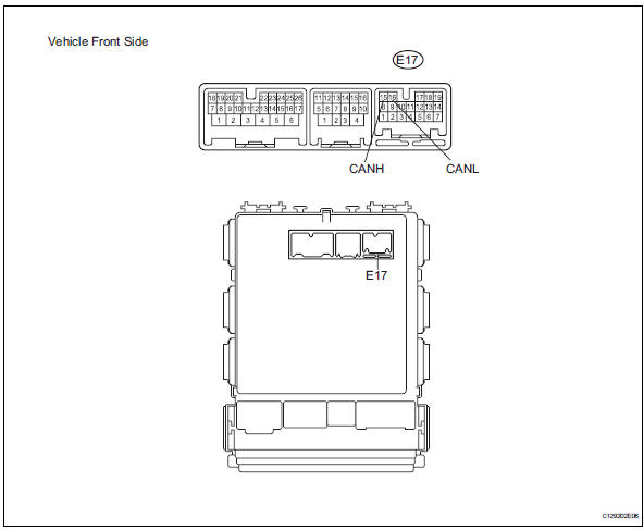
- Disconnect the 1b and 1e junction block connectors.
- Disconnect the e17 ecu connector.
- Measure the resistance of the wire harness side connectors.
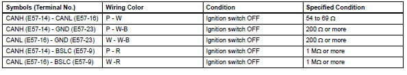
- Check 4wd control ecu (for 4wd)
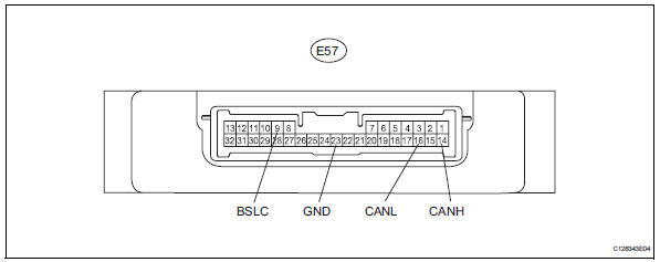
- Disconnect the e57 ecu connector.
- Measure the resistance of the wire harness side connector.
 Problem symptoms table
(2005/11-2006/01)
(2006/01- )
Hint:
*: For 4wd ...
 Check 4wd control ecu (for 4wd)
Notice:
Turn the ignition switch off before measuring the
resistances of the main wire and branch wire.
After the ignition switch is turned off, check that the
key reminder warning system an ...
Other materials:
Sensor detection display,
object distance
â– Detection range of the sensors
Approximately 3.3 ft. (100
cm)
Approximately 4.9 ft. (150
cm)
Approximately 2.1 ft. (63 cm)
The diagram shows the detection
range of the sensors. Note that the
sensors cannot detect objects that are extremely close to the vehicle.
The range of the sensors ...
Replacement
Replace timing chain cover oil seal
Hint:
There are 2 methods to replace the oil seal.
If the timing chain cover is removed from the
cylinder block:
Using a screwdriver and hammer, tap out the
oil seal.
Apply multi-purpose grease to the lip of a new
oil seal.
Notice:
...
Wiper switch
Precaution
Precaution for vehicle with srs
Some procedures in this section may affect the
supplemental restraint system (srs). Prior to
performing the procedures, read the srs section's
"precaution" (see page ss-2).
Components
Removal
Disconnect cable from negat ...
