Toyota RAV4 (XA40) 2013-2018 Service Manual: Second brake piston
Components
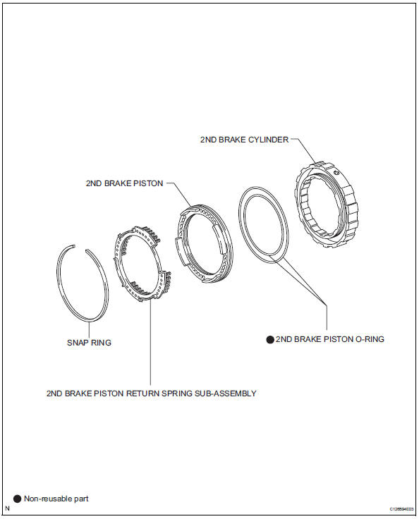
Disassembly
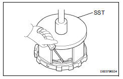
- Remove 2nd brake piston return spring sub-assembly
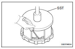
- Place sst on the return spring and compress.
- Using a screwdriver, pry out the snap ring.
- Remove the piston return spring.
- Inspect 2nd brake piston return spring sub-assembly (see page ax-223)
- Remove 2nd brake piston
- Hold the 2nd brake piston and apply compressed air (392 kpa, 4.0Kgf/cm2, 57 psi) to the 2nd brake cylinder to remove the 2nd brake piston.
- Remove 2nd brake piston o-ring
- Remove the 2 o-rings from the 2nd brake piston.
Inspection
- Inspect 2nd brake piston return spring sub-assembly
- Using a vernier caliper, measure the free length of the spring together with the spring seat.
Standard free length: 16.61 Mm (0.6539 In.)
Reassembly
- Install 2nd brake piston o-ring
- Coat the 2 new o-rings with atf, and install them into the 2nd brake piston.
- Install 2nd brake piston
- Press in the 2nd brake piston into the 2nd brake cylinder with your hands.
- Install 2nd brake piston return spring sub-assembly
- Install the piston return spring.
- Place sst on the piston return spring, and compress the piston return spring with a press.
Sst 09387-00060
- Using a screwdriver, install the snap ring.
Notice:
Be sure the end gap of the snap ring is not aligned with the piston return spring claw.
 Reassembly
Install front oil pump oil seal
Using sst and a hammer, install a new oil seal to
the pump.
Sst 09350-32014 (09351-32140)
Hint:
The seal end should be flat with the outer edge of
...
 Forward clutch
Components
Disassembly
Inspect forward clutch (see page ax-227)
Remove forward multiple disc clutch disc
Using a screwdriver, remove the snap ring.
Remove the flange , 5 discs a ...
Other materials:
Tc and cg terminal circuit
Description
Dtc output mode is set by connecting terminals 13 (tc) and 4 (cg) of the
dlc3. The dtcs are indicated
by the blinking of the tire pressure warning light.
Wiring diagram
Hint:
When each warning light continues blinking, a ground short in the wiring of
terminal tc of the dlc3 ...
Rear differential carrier assembly
Components
...
Heated steering wheel/seat
heaters/seat ventilators
Heated steering wheel
Warm up the grip of the steering
wheel
Seat heaters
Warm up the seat upholstery
Seat ventilators
Maintain good ventilation by
pulling air through the seat
upholstery
WARNING
â– To prevent minor burn injuries
Care should be taken if anyone in
the following categories ...
