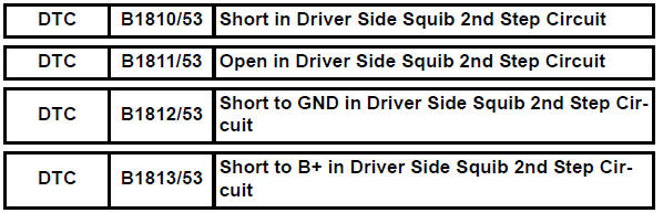
Toyota RAV4 (XA40) 2013-2018 Service Manual: Short in driver side squib 2nd step circuit
Description
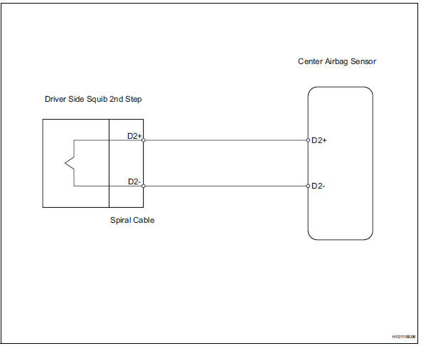
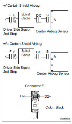
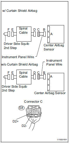
The driver side squib 2nd step circuit consists of the center airbag sensor, the spiral cable and the steering pad.
The circuit instructs the srs to deploy when the deployment conditions are met.
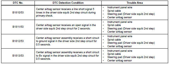
These dtcs are recorded when a malfunction is detected in the driver side squib 2nd step circuit.
Wiring diagram
Inspection procedure
Hint:
- Perform the simulation method by selecting the "check mode" (signal check) with the intelligent tester (see page rs-52).
- After selecting the "check mode" (signal check), perform the simulation method by wiggling each connector of the airbag system or driving the vehicle on a city or rough road (see page rs-52).
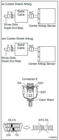
- Check steering pad (driver side squib 2nd step)
- Turn the ignition switch off.
- Disconnect the cable from the negative (-) battery terminal, and wait for at least 90 seconds.
- Disconnect the connectors from the steering pad.
- Connect the white wire side of sst to the spiral cable connector e.
Caution:
Never connect a tester to the steering pad (driver side squib 2nd step) for measurement, as this may lead to a serious injury due to airbag deployment.
Notice:
- Do not forcibly insert sst into the terminals of the connector when connecting.
- Insert sst straight into the terminals of the connector.
Sst 09843-18060
- Connect the cable to the negative (-) battery terminal, and wait for at least 2 seconds.
- Turn the ignition switch on, and wait for at least 60 seconds.
- Clear the dtcs (see page rs-49).
- Turn the ignition switch off.
- Turn the ignition switch on, and wait for at least 60 seconds
- Check the dtcs (see page rs-49).
Ok: dtc b1810, b1811, b1812, b1813 or 53 is not output.
Hint:
Dtcs other than dtc b1810, b1811, b1812, b1813 or 53 may be output at this time, but they are not related to this check.


- Check connector
- Turn the ignition switch off.
- Disconnect the cable from the negative (-) battery terminal, and wait for at least 90 seconds.
- Disconnect sst from the spiral cable.
- Check that the spiral cable connector (on the steering pad side) is not damaged.
Ok: lock button is not disengaged, and claw of lock is not deformed or damaged.


- Check driver side squib 2nd step circuit
- Disconnect the connector from the center airbag sensor.
- Connect the cable to the negative (-) battery terminal, and wait for at least 2 seconds.
- Turn the ignition switch on.
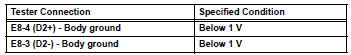
- Measure the voltage of the wire harness side connector.
Standard voltage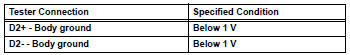
- Turn the ignition switch off.
- Disconnect the cable from the negative (-) battery terminal, and wait for at least 90 seconds.
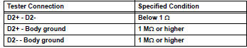
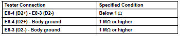
- Measure the resistance of the wire harness side connector.
Standard resistance
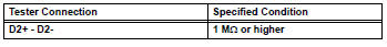
- Release the activation prevention mechanism built into connector b (see page rs-37).
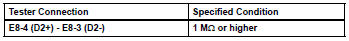
- Measure the resistance of the wire harness side connector.
Standard resistance

- Check instrument panel wire
- Restore the released activation prevention mechanism of connector b to its original position.
- Disconnect the instrument panel wire connector from the spiral cable.
- Connect the cable to the negative (-) battery terminal, and wait for at least 2 seconds.
- Turn the ignition switch on.
- Measure the voltage of the wire harness side connector.
Standard voltage
- Turn the ignition switch off.
- Disconnect the cable from the negative (-) battery terminal, and wait for at least 90 seconds.
- Measure the resistance of the wire harness side connector.
Standard resistance
- Release the activation prevention mechanism built into connector b (see page rs-37).
- Measure the resistance of the wire harness side connector.
Standard resistance

Replace spiral cable
 Short in front passenger side squib circuit
Description
The front passenger side squib circuit consists of the center airbag sensor
and the front passenger airbag.
The circuit instructs the srs to deploy when the deployment conditions ...
 Short in front passenger side squib 2nd step circuit
Description
The front passenger side squib 2nd step circuit consists of the center airbag
sensor and the front
passenger airbag.
The circuit instructs the srs to deploy when the deployment ...
Other materials:
Opening/closing the back
door (vehicles with power
back door)
â– Using the wireless remote
control
Press and hold the switch.
The power back door automatically
opens/closes.
Pressing the switch while the power
back door is opening/closing stops
the operation. When the switch is
pressed and held again during the
halted operation, the back door will
perform t ...
RCTA function
â– Operation of the RCTA
function
The RCTA function uses rear
side radar sensors to detect
vehicles approaching from the right or left at the rear of the
vehicle and alerts the driver of
the presence of such vehicles
by flashing the outside rear view
mirror indicators and sounding a
buzzer.
Appr ...
Diagnosis system
Check dlc3
Check the dlc3:
the power steering ecu uses can (iso11898-1)
and iso9141-2 for communication protocol. The
terminal arrangement of the dlc3 complies with
sae j1962 and matches the iso9141-2 format.
Notice:
*: Before measuring the resistance, leave the
vehicle ...
