Toyota RAV4 (XA40) 2013-2018 Service Manual: Short in front passenger side squib 2nd step circuit
Description
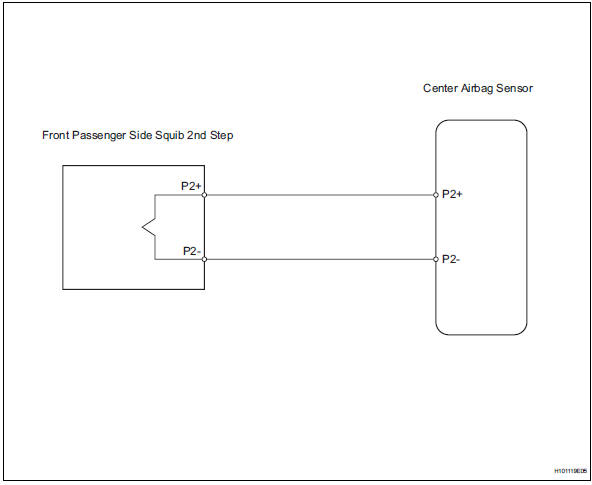
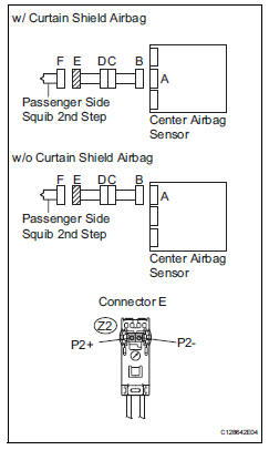
The front passenger side squib 2nd step circuit consists of the center airbag sensor and the front passenger airbag.
The circuit instructs the srs to deploy when the deployment conditions are met.
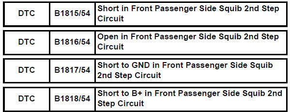
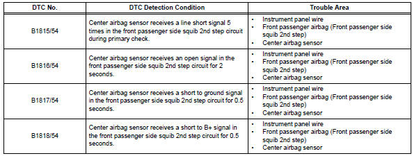
These dtcs are recorded when a malfunction is detected in the front passenger side squib 2nd step circuit.
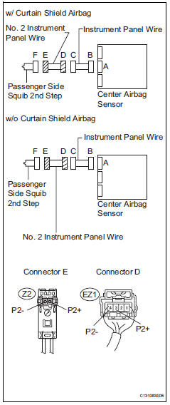
Wiring diagram
Inspection procedure
Hint:
- Perform the simulation method by selecting the "check mode" (signal check) with the intelligent tester (see page rs-52).
- After selecting the "check mode" (signal check), perform the simulation method by wiggling each connector of the airbag system or driving the vehicle on a city or rough road (see page rs-52).
- Check front passenger airbag assembly (front passenger side squib 2nd step)
- Turn the ignition switch off.
- Disconnect the cable from the negative (-) battery terminal, and wait for at least 90 seconds.
- Disconnect the connector from the front passenger airbag.
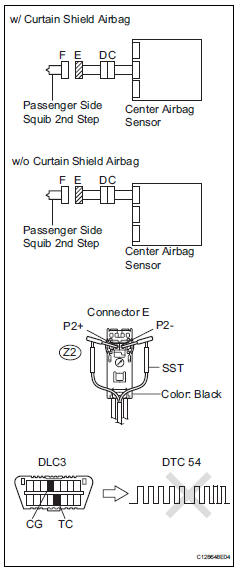
- Connect the white wire side of sst to the instrument panel wire connector e.
Caution:
never connect a tester to the front passenger airbag (front passenger side squib 2nd step) for measurement, as this may lead to a serious injury due to airbag deployment.
Notice:
- Do not forcibly insert sst into the terminals of the connector when connecting.
- Insert sst straight into the terminals of the connector.
Sst 09843-18060
- Connect the cable to the negative (-) battery terminal, and wait for at least 2 seconds.
- Turn the ignition switch on, and wait for at least 60 seconds.
- Clear the dtcs (see page rs-49).
- Turn the ignition switch off
- Turn the ignition switch on, and wait for at least 60 seconds.
- Check the dtcs (see page rs-49).
Ok: dtc b1815, b1816, b1817, b1818 or 54 is not output.
Hint:
Dtcs other than dtc b1815, b1816, b1817, b1818 and 54 may be output at this time, but they are not related to this check.

- Check connector
- Turn the ignition switch off.
- Disconnect the cable from the negative (-) battery terminal, and wait for at least 90 seconds.
- Disconnect sst (resistance 2.1 Ù) from the instrument panel wire.
- Check that the instrument panel wire connectors (on the front passenger side airbag) are not damaged.
Ok: lock button is not disengaged, and claw of lock is not deformed or damaged.

- Check instrument panel wire
- Disconnect the connector from the center airbag sensor.
- Connect the cable to the negative (-) battery terminal, and wait for at least 2 seconds.
- Turn the ignition switch on.
- Measure the voltage of the wire harness side connector.
Standard voltage 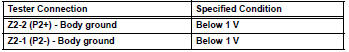
- Turn the ignition switch off
- Disconnect the cable from the negative (-) battery terminal, and wait for at least 90 seconds.
- Measure the resistance of the wire harness side connector.
Standard resistance 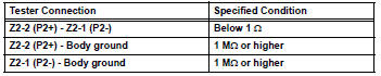
- Release the activation prevention mechanism built into connector b (see page rs-37).
- Measure the resistance of the wire harness side connector.
Standard resistance 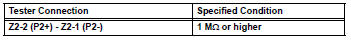

- Check no. 2 Instrument panel wire
- Disconnect the no. 2 Instrument panel wire connector from the instrument panel wire.
- Connect the cable to the negative (-) battery terminal, and wait for at least 2 seconds.
- Turn the ignition switch on.
- Measure the voltage of the wire harness side connector.
Standard voltage 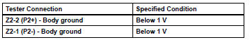
- Turn the ignition switch off.
- Disconnect the cable from the negative (-) battery terminal, and wait for at least 90 seconds.
- Measure the resistance of the wire harness side connector.
Standard resistance 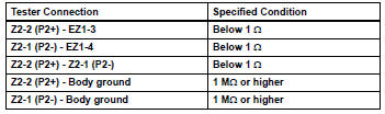

Repair or replace instrument panel wire
 Short in driver side squib 2nd step circuit
Description
The driver side squib 2nd step circuit consists of the center airbag sensor,
the spiral cable and the
steering pad.
The circuit instructs the srs to deploy when the deployment c ...
 Short in front driver side - side squib circuit
Description
The driver side - side squib circuit consists of the center airbag sensor and
the front seat side airbag lh.
This circuit instructs the srs to deploy when the deployment conditio ...
Other materials:
Vehicle load limits
Vehicle load limits include
total load capacity, seating
capacity, TWR (Trailer
Weight Rating) and cargo
capacity.
Total load capacity (vehicle
capacity weight):
Total load capacity means the
combined weight of occupants,
cargo and luggage.
Seating capacity:
Seating capacity means the
max ...
Display contents
Following information is displayed
on the multi-information
display.
Content display area (left)
Content display area (center)
Content display area (right)
Driving support system information
display area
When driving information support
system is displayed on the content
display area, the sy ...
Window lock switch
Press the switch to lock the passenger
window switches.
Use this switch to prevent children
from accidentally opening or closing
a passenger window.
The power windows can be operated when
Vehicles without a smart key system
The engine switch is in the “on” position.
Vehicles ...
